Skip to Main Content

What is a Microchip?

A microchip is an electronic device made of a small, flat piece of semiconductor material modified with other dopants, oxides, and metals to create electronic components, including transistors, diodes, resistors, and capacitors connected in a circuit.

Microchips are also called:

  • Integrated circuits (ICs)
  • Computer chips
  • Semiconductors
  • Chips

Integrated circuits have replaced assemblies of discrete components attached by wires or printed circuit boards (PCBs) because they are a single monolithic device that is much smaller, uses much less power, and can be mass produced at a significantly lower cost.

Semiconductor materials were discovered in 1821 by Thomas Johann Seebeck, and the first working semiconductor transistors were created by Willam Shockley in 1947. The components and all their interconnects were then combined into a single device in 1959 by Robert Noyce. The key to this invention and all that followed was the planar manufacturing process, which used photolithography to deposit and remove materials one layer at a time in a precise manner.

Integrated circuits are an integral part of modern life, providing electronics for devices ranging from toys to deep space probes. In 2023, the worldwide revenue from microchip sales was $526.9 billion. That year’s sales also saw further growth in chip usage beyond computers: 32% were for communication, 17% for automotive applications, 14% for industrial devices, 11% for consumer electronics, and only 25% for computing.

Driven by Moore’s Law, which states that the number of transistors in an IC will double every two years, the growing complexity of the circuits and the ever-decreasing size of components make designing and manufacturing microchips more challenging with each generation of chips.

The general size of individual elements on a chip, referred to as feature size, is measured in nanometers (nm), or one-billionth of a meter. Current semiconductor manufacturers use 14-nm, 10-nm, 7-nm, 5-nm, and 3-nm processes, with 2-nm technologies coming online. For scale, a grain of rice is 5 million nanometers long.

In 2023, researchers created a record-breaking microprocessor containing 1.2 trillion transistors. Intel’s line of CPUs in 2024 include more than 100 million transistors on a single chip.

The Elements of a Typical Microchip

Integrated circuits are made from semiconductor material, usually silicon, stacked in overlapping layers. Here are the most common elements in a microchip:

  • Silicon substrate: The base pure silicon crystal layer from which the other layers are constructed by removing or depositing other materials or doping the crystal material. 

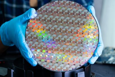
Silicon wafer for manufacturing semiconductor of integrated circuit.
  • Layers: Electronic circuits are created on individual layers. Layers are modified with photolithography, etching, and deposition to produce the desired components and interconnections. Some layers also serve as electrical insulators.
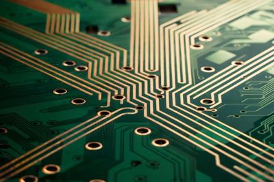
  • Vias: A conducting zone, usually cylindrical, used to transmit electrical signals between layers.
Close-up View of Green Printed Circuit Board with Copper Traces and Via Holes
  • Components: The electronic devices that make up the desired circuit. In most ICs, these consist of transistors, capacitors, diodes, resistors, and sometimes inductors.
  • Interconnects: Metalized paths on a given layer that conduct electricity between components or to vias. 
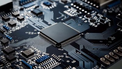
Close-up of a circuit board, containing integrated electronic components, including a processor and memory.
  • Packaging: Once completed, the IC is placed inside an assembly called a semiconductor package that protects and insulates the delicate silicon chip, can connect multiple chips, and provides a way to connect the chip or chips to a larger electronics circuit. 

How Microchips Are Manufactured

There are three steps to microchip manufacturing. Each step is highly optimized and automated to minimize cost, ensure quality, and maximize efficiency. Engineers designing ICs need to have a good understanding of the manufacturing process because each step determines the size, shape, and spacing of the components.

Step 1: Wafer Production

Making blank silicon wafers is the first step in semiconductor manufacturing. This process begins by growing a monocrystalline cylindrical ingot, called a boule, of semiconductor material, usually pure silicon. The boule is then sliced into a thin wafer, machined to create a flat surface, chemically etched to remove any damage from the machining, and polished. Electronic wafers are usually 100 to 450 mm in diameter. The most common size is 300 mm across and 755 µm thick.

Step 2: Fabrication

The circuitry, with all its components and interconnects, is created in a semiconductor fabrication facility, usually called a fab. Each layer and the topology of the circuitry is created in a series of highly controlled steps. Robots move wafers from machine to machine in clusters. Most chip fabrication processes follow these steps for each layer:

  • Grow a silicon dioxide layer to cover the layer completely (also called passivation).
  • Add a photoresist coating.
  • Expose the photoresist layer to ultraviolet light in the pattern of the geometry you want to create. The photoresist layer is then developed, and the material exposed to light is removed. This is called photolithography.
  • Use chemicals, usually a strong acid, to remove the oxide layer where the photoresist was removed. This is referred to as etching.
  • Remove the undeveloped photoresist material.
  • If doping is needed for the layer, ion implantation of contaminants into the crystal structure creates the desired semiconductor behavior for transistors and other components.
  • For other materials, various forms of chemical or vapor deposition are used to create interconnects, vias, and other components.

Step 3: Packaging

Once each layer has been constructed and the wafer is cleaned and tested, it is cut into individual chips called dies. One or more dies are then attached to a structure through bonding, and the IC is encapsulated in different materials, depending on the application. Some packages contain a single chip, but the current trend is to combine multiple dies in a single package. 

Microchip Types and Uses

The types and uses of integrated circuits are growing every year. Early ICs often performed a single function. But as the manufacturing technology and design tools have improved, chips have shifted to being multifunction.

Smartphones are a great example of how multiple types of chips can be combined in a single device for different uses. They contain radio frequency (RF) chips for the 5G radio and GPS, optoelectrical chips for the cameras, LED chips for the display, digital ICs for the processing units, micro-electromechanical systems (MEMS) chips for the accelerometer, and a dozen other integrated circuits to sense, control, and modify a vast number of uses.

The different types of chips can be categorized by the signaling they carry out.

Analog Integrated Circuits

Analog signals carry voltage across a continuous voltage range, not just a high or a low voltage signal. They are used to amplify, filter by frequency, and mix signals. The frequency and power of an analog IC can vary greatly, and higher frequencies and higher powers present significant design challenges.

Common uses for analog ICs include:

  • Optical, thermal, and audio sensors
  • Power management circuits
  • Operational amplifiers (op-amps)
  • Audio and video signal processing
  • Telecommunications, including radio communication and optical signal processing
  • RF circuits
  • Signal conditioning
  • Machine controllers

Digital Integrated Circuits

Digital ICs are logic devices that contain millions or billions of logic gates made of transistors. A signal running at a fixed clock frequency is modified or measured as either high or low, zero or one. By combining different logic devices, very complex calculations can be done with very little power used.

Some of the most common uses for digital ICs include:

  • Logic ICs or processors
    • Microprocessors
    • Microcontrollers
    • Application-specific integrated circuits (ASICs)
  • Memory chips
  • Field programmable gate arrays (FPGAs)
  • Digital power management devices
  • System-on-a-chip (SoC) devices
  • Multi-die chips

Mixed-signal Integrated Circuits

Some integrated circuits combine circuitry to handle analog and digital signals and convert between the two to create mixed-signal integrated circuits. They are used when an analog signal is sensed or created and logical operations are needed to read, create, or modify that signal.

Some of the most common uses for mixed-signal ICs are:

Future Trends in Microchip Technology

The future of microchips looks like the past, with more capabilities in smaller sizes while constantly driving the cost down. Advances in manufacturing will also create new opportunities for better performance and new applications.

Trends that will drive electrical engineering design and simulation in the near future include:

Shift to Fabless Design and Foundries

The industry has shifted over the years to a model where companies can design their own ICs and then outsource the manufacturing to a company that just makes chips. This is called fabless design, and the contract manufacturers are called foundries. This enables companies like Apple and Qualcomm to design innovative new products without the capital investment of building their own fabrication facilities. Engineers must design to the manufacturing processes and standards of the foundry they will use.

Smaller Feature Size

Feature sizes continue to shrink, creating power and signal integrity issues. To stay competitive, electrical engineers need to design using these new capabilities, as well as leveraging simulation and design best practices to avoid issues.

Electronic Device Complexity and Combined Functionality

With time, an increasing number of designers of electronic devices are looking for greater functionality in a single chip. Internet of Things (IoT) devices, new solid-state long-term storage, and GPU chips are examples of integrated circuits that will not only add new features and capabilities in the same chip, but the interaction between those functions will also become more sophisticated. Engineers need design and simulation tools to drive designs in which the industry is pulling the technology. Biomedical electronics like implanted microchips will be another area in which several capabilities are needed on a single chip.

Higher Clock Speeds and Frequencies

Increased performance demands and advances in RF technology are driving up clock speeds for digital ICs and frequencies for analog and mixed-signal chips. Both create issues with signal integrity and power management.

Greater Computer Power With Increased Energy Efficiency

The growth of data centers for high-performance computing to support trends like artificial intelligence, cryptocurrency mining, and IoT applications is driving demand for increased performance for microprocessors. These applications are pushing the industry for improvements in FPGAs, solid-state hard drives, memory, and GPUs, along with all the chips needed to connect everything at increasing data transfer speeds.

More Use Beyond Computing

The trend of increased microchip use in automotive, consumer electronics, and industrial applications will continue. Almost all products will be designed as smart devices with connectivity to broadband, sensors, and computing power — all of which need microchips. 

Simulation in the Design of Microchips

The complexity and expense of microchip manufacturing make physically prototyping designs impractical. Instead, engineers use virtual prototyping through simulation to drive their design, verify the performance, and identify and solve problems before production begins. Simulation is also used to design packaging and optimize the semiconductor manufacturing machines that make the chips.

Using simulation for digital microchips begins with verifying the logical functionality of the digital design at an abstract level with RTL design. This includes a first look at power management with Ansys PowerArtist™ software. This tool can assess the power needs of a design early in the process and help drive a more power-efficient design.

Once the physical design is laid out, engineers can use Ansys RedHawk-SC™ software, the trusted industry leader for power noise and reliability for digital ICs, to assess voltage drop and electromigration in their designs.

On the analog and mixed-signal side of things, Ansys Totem™ software can be brought into the process for power integrity and reliability signoff. The industry’s trusted gold standard for electromigration multiphysics, it is certified by all major foundries down to 3 nm. It also works with Ansys PathFinder-SC™ software to calculate electrostatic discharge.

Once the design is optimized and verified, packaging engineers can use simulation to optimize the power, signal integrity, and robustness of the full microchip package. RedHawk-SC software is designed to handle large, multichip configurations, including system-in-package designs. Advanced semiconductor packaging uses 2.5D- and 3D-IC approaches to combine and connect multiple dies in the same package, and simulation with RedHawk-SC software is the primary way to verify and optimize the designs.

Once the electrical aspects of the design are resolved, packaging engineers can use tools like Ansys Mechanical™software and the Ansys Icepak® tool for structural reliability and thermal management.

Related Resources

Leveraging Chip Power Models for System-Level EMC Simulation of Automotive ICs

Learn how integrated circuit (IC), package and board designers can leverage Ansys chip models in system-level simulations to meet the strict EMC requirements.

The Benefits and Risks of Copper Pillar Bumped Flip Chips

Discover the benefits and risks of copper pillar bumped flip chips.

How Multiphysics Simulation Enables 3D-IC Implementation at the Speed of Light

Learn how chip designers are breaking down barriers to 3D-IC development with novel multiphysics simulation capabilities.