-
United States -
United Kingdom -
India -
France -
Deutschland -
Italia -
日本 -
대한민국 -
中国 -
台灣
-
Ansysは、シミュレーションエンジニアリングソフトウェアを学生に無償で提供することで、未来を拓く学生たちの助けとなることを目指しています。
-
Ansysは、シミュレーションエンジニアリングソフトウェアを学生に無償で提供することで、未来を拓く学生たちの助けとなることを目指しています。
-
Ansysは、シミュレーションエンジニアリングソフトウェアを学生に無償で提供することで、未来を拓く学生たちの助けとなることを目指しています。
ANSYS ADVANTAGE MAGAZINE
DATE: 2020
Rapidly Meet Heat Exchanger Regulations
By Richard Grant, President, Grantec Engineering Consultants Inc., Halifax, Canada
Because of the potential for high operational pressures and the consequences of failure (which could include personal injury, equipment loss, and/or decreased output and revenue), shell-and-tube heat exchangers are classified as pressure vessels. Pressure vessels are strictly regulated in North America and elsewhere in the world. To commission a new design requires regulatory approval. Heat exchangers with symmetric tube layouts can typically be assessed using codes such as the American Society of Mechanical Engineers (ASME) Boiler and Pressure Vessel Code (BPVC). However, for exchangers with highly asymmetric tube layouts, simulation is often the only cost-effective way to qualify these designs. Ansys Mechanical software was recently used by Grantec Engineering to perform finite element analysis (FEA)-based strength assessments for a range of condenser and evaporator heat exchangers to gain rapid approval from regulatory authorities.
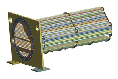
An Ansys Mechanical model of a heat exchanger
A decade or two ago, nearly all heat exchangers were designed with symmetric tubesheet layouts that were relatively simple to design and validate. However, symmetrical designs can be inefficient if the flow through both the tubes and the shell is unevenly distributed, resulting in wasted thermal energy.
In recent years, computational fluid dynamics (CFD) software, such as Ansys Fluent, has simplified the process of simulating the flow of fluid through both sections of the heat exchanger. Engineers obtain key insights like the flow distribution in the tube and shell, recirculation zones, areas of greater and lesser heat transfer, temperature of the casing, pressure on the casing, etc.
This information makes it practical to optimize heat transfer capacity and pressure drop by designing the shell-and-tube layout for more uniform and efficient flow patterns. The resulting asymmetric design provides substantial improvements in performance over the life of the heat exchanger.
Grantec was retained to evaluate the design of numerous heat exchangers for a large international manufacturer of heating, ventilation and air conditioning (HVAC) equipment. These assessments needed to be performed based on the ASME BPVC requirements. Before the equipment could be marketed in Canada, it also needed to meet the Canadian requirements for pressure vessels, including requirements contained within the Canadian Standards Association (CSA) B51 “Boiler and Pressure Vessel Code.” To assure compliance with both the ASME and the CSA B51 requirements, Grantec simulated the designs with Ansys Mechanical because the software handles very complex nonlinear mixed-mesh models that have a large number of contacts.
HEAT EXCHANGER ASSESSMENT
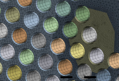
Grantec assessed numerous exchanger configurations with varying parameters, including a range of different shell diameters and exchanger lengths, and multiple tubesheet arrangements ranging from about 200 to 500 tubes. Many of the tubesheet arrangements were highly asymmetrical so compliance could not be assessed with the ASME code equations, which are mainly applicable to symmetric tubesheet patterns. Some of the models developed had as many as 500 contact regions. Further, the tubes in these heat exchangers are not smooth, but have both internal and external fins to increase the surface available for heat transfer.
Simulation models were developed to assess the effect of the fins on the longitudinal and radial moduli and the Poisson effect. The Poisson effect (the same effect that causes a rubber band to become thinner as you pull on it) causes the tubes to contract longitudinally as they are internally pressured and expand longitudinally as they are externally pressured. For the exchangers considered, the tubes are “rolled” (i.e., expanded) into the tubesheets at both ends of the heat exchanger. Baffle plates used to support the tubes are held in position with tie rods that also thermally expand.
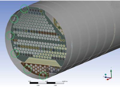
Connections between tubesheet and shell. The baffle-to-shell welds are circled.
The model developed included contacts between the tubes and the baffle plates, and contacts between the baffle plates and the external exchanger shell. This idealization provided support to the tubes and permitted differential thermal expansion between the tubes, the baffle plates and the shell. The arrangement resulted in an accurate model of the restraints, forces and stresses generated, which was necessary to qualify the design.
Ansys Mechanical makes it easy to calculate forces at any point in the domain.
CALCULATING VALUES REQUIRED FOR REGULATORY APPROVAL
Many FEA software packages are unable to address some or all of these issues and have difficulty in converging the large, complex models required to address them. The manufacturer originally tried simulating the design with software integrated into a computer-aided design system. That software was not well-suited for the complex arrangement with so many contacts. Using Mechanical for pressure vessel and exchanger analysis provides the robustness and reliability needed to solve the large, complex models. Mechanical software contains stress linearization tools that separate stresses through a section into membrane, bending and peak stresses. For a cantilevered plate, the membrane stress results from a tensile load while the bending stress is generated by applying a load normal to the cantilever. Mechanical makes it easy to calculate these stresses at any point in the domain. The software also has advanced fracture mechanics simulation capabilities, which are used by Grantec for fitness of service assessment of pressure and structural components.
The Grantec analysis reports resulted in fast approval of the heat exchanger designs by the regulatory authorities.
Grantec engineers applied Mechanical to assess the heat exchanger based on ASME BPVC Section VIII Division 1 – Part UHX requirements, including the multiple load cases required for each exchanger configuration. The models also included the corrosion allowance stipulated by the manufacturer. Engineers used solid elements to model the tubesheet, exchanger supports and welds, and the portion of the tubes in the vicinity of the tubesheet for greater accuracy. To improve computational efficiency, shell elements were employed to model the remainder of the shell and tubes, along with the baffle plates. The properties of the shell elements used for the tubes were modified to reflect the moduli and Poisson’s ratio derived from the separate analysis of the finned tubes. Frictionless contacts for the model were used at partition plates so that tube support and thermal growth could be accurately simulated. The Grantec team modeled connections with various contact conditions including bonded, no separation and frictionless. The team applied pressure and thermal loads to the models. The weight of the components and tube fluid was considered using gravity load while engineers accounted for the weight of the shell fluid and static head with a hydrostatic pressure load. Gasket and bolt loads were also included in the models at the end head locations.
Hydrostatic pressure in shell
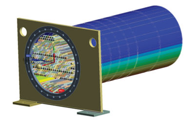
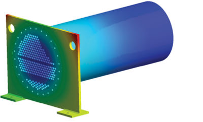
Deformation simulation using Ansys Mechanical
FAST REGULATORY APPROVAL
Grantec engineers solved the models using the Ansys High-Performance Computing (HPC) software suite on a 16-core HPC platform. The use of Ansys HPC proved effective in reducing the analysis run times for the computationally demanding analysis, some of which had upward of 500 contacts and thus were highly nonlinear.
In addition to the ASME requirements, the analysis was performed and documented as required by the Canadian Standards Association (CSA) B51-14 Boiler and Pressure Vessel Code, Annex J: Finite Element Analysis Requirements. The Annex J requirements include demonstration and documentation of the validity of the FE analysis results. Among them is the demonstration that stress results have converged. As a result of using the Ansys HPC software, Grantec was able to quickly perform numerous analyses with focused mesh refinement in areas exhibiting high stresses to confirm convergence and the acceptability of the stress levels.
The Grantec analysis reports resulted in fast approval of the heat exchanger designs by the regulatory authorities. During their review, a technical specialist working for the regulatory agency commended Grantec for the thoroughness and completeness of the submission.
NOTE
Grantec’s Richard Grant is a member of the CSA B51 committee and has contributed to the authoring of the Annex J Finite Element Analysis Requirements published in the 2014 and 2019 editions of CSA B51.
さあ、始めましょう
エンジニアリング課題に直面している場合は、当社のチームが支援します。豊富な経験と革新へのコミットメントを持つ当社に、ぜひご連絡ください。協力して、エンジニアリングの障害を成長と成功の機会に変えましょう。ぜひ今すぐお問い合わせください。


