


トピックの詳細
シグナルインテグリティとは
システムのシグナルインテグリティ(SI)は、回路への入出力時に電気信号がどの程度変化するかを示す指標です。デジタルエレクトロニクスの場合、信号は電流であり、電圧は時間の経過とともにハイとローの値間で変化します。
シグナルインテグリティは、最新のあらゆる電子システムにおいて基礎的な指標となります。エレクトロニクス業界で「インテグリティ」という用語は、ある規定に沿って、その状態が損なわれず、完全で分割されていないことを意味します。クロストーク、インピーダンス不整合、損失などによって信号の波形が元の波形と大きく異なる場合、レシーバは信号を読み取ることができず、シグナルインテグリティの問題が発生します。そのため、シグナルインテグリティの問題を解析して改善するシグナルインテグリティエンジニアリングは、集積回路(IC)、ICパッケージ、プリント回路基板(PCB)の設計において重要となります。
信号速度の向上とPCBやパッケージの縮小化により、シグナルインテグリティ問題への対処はさらに困難になります。高速デジタル信号と小さなジオメトリにより、信号のノイズや歪みはより顕著になります。一方で、問題が大きくなるにつれて、対処方法に関する業界の理解も深まり、エンジニアが電子システムの定義、シミュレーション、調整に使用できるツールの機能も高くなります。
信号の波形の歪み、ノイズ、時間のシフト、振幅の減少は、材料内の抵抗、電子の移動によって生じる電磁界、他の電磁界から誘起される電流、および回路の静電容量が原因で、電子がドライバーからレシーバに流れるときに発生します。PCBでは、材料、回路を形成するトレースの形状、さまざまな層の配置と厚さ、層間での電流の伝達方法によって、これらの効果や影響が促進されます。
また、パワーインテグリティに分類され、密接に関連するその他の問題もあります。シグナルインテグリティでは、PCB内の信号の忠実度に着目するのに対して、パワーインテグリティでは、これらの信号を送受信するコンポーネントに供給される電力の品質に着目します。シグナルインテグリティに影響するインピーダンス、インダクタンス、減衰と同じ問題がパワーインテグリティにも影響を及ぼします。また、一方の変更が他方に悪影響を及ぼすこともあるため、エンジニアは設計を改善する際に両方をシミュレーションして測定する必要があります。
シグナルインテグリティが重要な理由
シグナルインテグリティに対処できなければ、デジタルデバイスで大きな問題が発生します。最も深刻な問題は、信号の歪みが極めて大きくなり、回路を介して送信された0または1が正しく受信されず、バイナリ値が間違っているときに発生します。また、ノイズや時間の遅れが大きい場合にデバイスが故障することもあります。現在の非常に複雑なPCBでは、数百のPCBトレースが実装されているため、シグナルインテグリティの問題が生じている信号経路が1つでもあれば、基板全体が機能しなくなります。
現実的には、回路を介して信号を送信した場合に、受信側に到達するまでに信号に何も変化がないことはあり得ません。設計チームは、シングルインテグリティ(SI)解析の基礎を深く理解し、SIが最新の回路設計に与える影響を把握して、シグナルインテグリティの問題を突き止めて対処する方法を理解することで、デバイス全体のシングルインテグリティの低下を最小限に抑え、より小さなフォームファクターとより高い周波数を目指すことができます。
シグナルインテグリティ解析の基礎
シグナルインテグリティは、材料内を移動する電子の周囲の物理現象によって低下します。Maxwellの方程式は、電荷と電流の関係、電流によって電磁界がどのように生じるか、さらには電磁界によって電流がどのように変化するかを表しています。
つまり、PCB内のインターコネクト(デジタル信号では「伝送線」と呼ばれる)は、アンテナ、抵抗器、コンデンサのように機能します。信号の特性、導電性材料や誘電材料の材料特性、ジオメトリ、およびPCB内の回路や層の相対位置によって、Maxwellの方程式で記述される物理現象の大きさと影響が決まります。
シグナルインテグリティ問題の4つのタイプ
上記の基本的な物理特性により、シグナルインテグリティの問題は次の4つのカテゴリのいずれかに分類されます。
1. 電磁干渉(EMI)/電磁両立性(EMC)
高周波回路では、ジオメトリと周波数の組み合わせによっては、トレースやビアが信号を送信するアンテナとなります。しかし、この信号は、同じPCB上や他のデバイス内の他の回路、あるいは同じデバイスまたは近くのデバイスのコネクタやケーブルと結合する可能性があります。別の回路が干渉を受けると、電磁界のエネルギーが電流を誘起して、その信号にノイズを生じさせます。電磁波を送信した場合も、電磁界の発生によって電力が消費されるため、信号の電圧が低下します。そのため、設計者は電磁干渉(EMI)を最小限に抑え、開発中のデバイスが運用される電磁環境と互換性があること(電磁両立性(EMC))を確認する必要があります。
2.クロストーク
クロストークも、電磁相互作用の別の形態です。クロストークは、近接する複数の高速トレースの信号によって、それぞれの電界や磁界が結合したときに発生します。不要な信号は、隣接する伝送線(ヴィクティムトレース)上の信号と結合する「アグレッサートレース」と呼ばれる伝送線から生じます。以下のタイプの結合が発生します。
- 容量結合: アグレッサー回路の電界がヴィクティム回路に電圧を誘導することによって発生します。
- 磁界結合(電磁誘導): アグレッサー回路の磁界がヴィクティム回路に電圧を誘導することによって発生します。
- 導電結合: 接地面のリターンパス上で結合する両方の信号の電流によって発生します。
3.同時スイッチングノイズ(SSN)によるグランドバウンス
グランドバウンスは、PCBの信号グランドが全ポイントで同じではない場合に発生します。これは、複数の回路がハイ状態またはロー状態の間で電圧を同時に変化させ、接地面で電圧が上昇することによって引き起こされるシグナルインテグリティの問題です。これにより、ロー状態の電圧、つまりバイナリ信号の0が予想よりも高くなります。場合によっては、バウンスが比較的大きいために誤ったハイ状態として読み取られることがあります。
4.インピーダンス不整合
設計者は、交流電流(AC)回路のインピーダンスを考慮しなければなりません。インピーダンスとは、電流の流れに対する抵抗であり、インダクタンスと静電容量によって生じる電流の変化です。インピーダンス不整合は、回路のどこかでインピーダンスが変化すると発生します。この不整合により、信号の一部が反射して戻り、減衰するまで伝播を繰り返します。信号にノイズが加わるだけでなく、インピーダンス不整合によってタイミングに不確かさ(「ジッタ」と呼ばれる)が生じます。インピーダンス不整合を評価する標準的なツールは、時間領域反射法(TDR: Time-Domain Reflectometry)です。TDR法では、伝送線内の反射を測定します。
アイダイアグラム解析によるシグナルインテグリティの可視化
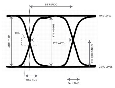
アイダイアグラム解析は、シグナルインテグリティの調査に使用される最も一般的なツールの1つです。アイダイアグラムは、「アイパターン」とも呼ばれ、デジタル回路の応答を時間の経過とともに表示する方法です。解析対象となる回路に繰り返し信号が入力され、時間の経過とともに出力信号が測定されます。データの各ビットは、X軸が時間、Y軸が振幅のグラフに重ね合わせた状態で表示されます。入力信号は矩形波であるため、完全な回路では、上下に2本の水平線、中央に2本の垂直線が表示され、水平方向では1ビットのデータ長さで分離され、垂直方向では信号の電圧差で分離された波形が示されます。
しかし、完璧な回路というものは存在しないので、実際は目のような形が現れます。前述のシグナルインテグリティの問題は、直線からの歪みとして現れます。以下の図は、回路における問題を明らかにする一般的な値を示しています。立ち上がり時間、立ち下がり時間、ジッタ、アイクロス比率などの値によって、信号がどのように歪むか、さらにはシステムに侵入するノイズが信号に与える影響などが明らかになります。
配線、ジオメトリ、または材料の変更前後のアイダイアグラムを比較することで、こうした変更が回路のシグナルインテグリティをどのように改善するかを確認できるようになります。
この解析アプローチは、当初はオシロスコープを使用して回路のシグナルインテグリティを迅速に可視化するために開発されました。現在、エンジニアはアイダイアグラムを使用して、シミュレーションで予測された回路の性能を調べています。これにより、設計者はさまざまな変更を迅速に試して、PCBのプロトタイプを作製する前に影響を確認できるようになりました。
シグナルインテグリティと集積回路(IC)
この記事では、PCBにおけるSIに焦点を当てていますが、ICチップにおけるシグナルインテグリティも重要です。フィーチャーサイズはさらに小さく、データレートはさらに高いため、集積回路をレイアウトしてインターコネクトを定義する際には、シグナルインテグリティがさらに重要な考慮事項となります。他の信号のスイッチングによる結合効果は、チップにおけるSI問題の最大の要因です。また、チップのすぐ外側では、パッケージへのインターコネクトとして機能するワイヤがすぐ近くに配線されているため、クロストークによる影響を大きく受けます。
ICチップのプロトタイプ作製は非常に困難です。したがって、潜在的な問題を特定して修正するために、設計プロセスのできる限り早い段階で、シミュレーションを使用してシグナルインテグリティとパワーインテグリティをモデル化します。チップは、製造プロセスを開始する前に、これらのツールを用いて検証し、期待どおりに動作するかどうかを確認する必要があります。
シグナルインテグリティの問題を特定して、性能を向上させるためのヒント
高速デジタル設計でSIの問題を回避するためにエンジニアが実行できる最も重要なステップは、PCB設計に対して確立された業界設計ルールに従うことです。一般的なルールとして、以下のものがあります。
- トレース間の距離を指定する
- トレース幅の急激な変化を避ける
- 許容されるコーナー半径内に収める
- トレースおよびビアスタブを避ける
- リターンパスを妨げるような不連続性をグランド層内に配置しない
- 差動ペアを同じ長さに設計する
- 電源層のインピーダンスを下げる
- 接地面の配置を慎重に検討し、PCBの各層を適切な厚さに設定する
- 高周波でのビアの使用を避ける
設計者がPCBレイアウトのすべての設計ルールに従った場合でも、問題が発生することがあります。また、複数のルール、製造上の制約、サイズの制限、コストに関する問題でバランスをとる場合にも問題が生じます。一般的に、こうした問題を特定して改善するために、シミュレーションが導入されます。
優れたパラメトリック設計と、PCBおよびパッケージの電磁界シミュレーションソフトウェアであるAnsys SIwave™や3D高周波シミュレーションソフトウェアであるAnsys HFSS™のようなロバストなシミュレーションツールセットを使用することで、エンジニアは迅速にトレードオフスタディを実行して解決策を導き出せます。
トレース内の電磁界や電流は、見たり、聞いたり、触ることができないため、シミュレーションを使用して、発生している場や流束を可視化します。こうして可視化することで、エンジニアは電磁界の伝播や信号のリターンパスを確認し、PCBやコンポーネント下の加熱を可視化して、トレースペア間のクロストークを確認できるようになります。
シグナルインテグリティの未来
SIの未来は、近年のデータレート、クロック速度、帯域幅要件の増大に似ています。パッケージングに関しては、より小型なPCBが採用されるようになり、PCBに実装されるコンポーネント数が増え、さらにはフレキシブルPCBを用いた複雑な形状の設計が増えることも考えられます。また、業界の需要を満たし、市場シェアを拡大するために、企業は新しい製造プロセスを導入して、さまざまな材料の実験を進めることでしょう。どちらもシグナルインテグリティに影響を及ぼします。
近い将来に加速すると思われる別の動きは、レイアウトとシミュレーションの緊密な統合です。これにより、設計プロセスのさらに早い段階で物理特性のシミュレーションが実行されます。エンジニアは、PCBの戦略を立てながら、設計の電磁界、パワーインテグリティ、熱特性、機械的なロバスト性を解析できるようになります。
他の分野と同様に、人工知能(AI)がシグナルインテグリティ問題を最小限に抑える上で大きな役割を果たすことでしょう。多くのレイアウトツールでは、回路図をPCBレイアウトに変換する際の配線ルールの適用において、古い形式のAIをすでに使用しています。次世代の生成AIツールを採用することで、設計ツールとシミュレーションツールの両方の機能が大幅に向上します。