-
United States -
United Kingdom -
India -
France -
Deutschland -
Italia -
日本 -
대한민국 -
中国 -
台灣
-
Ansysは、シミュレーションエンジニアリングソフトウェアを学生に無償で提供することで、未来を拓く学生たちの助けとなることを目指しています。
-
Ansysは、シミュレーションエンジニアリングソフトウェアを学生に無償で提供することで、未来を拓く学生たちの助けとなることを目指しています。
-
Ansysは、シミュレーションエンジニアリングソフトウェアを学生に無償で提供することで、未来を拓く学生たちの助けとなることを目指しています。
ANSYS BLOG
December 18, 2020
Solving Composites Design Challenges With Engineering Simulation
Increasingly, manufacturers are using composites to reliably solve real-world industry problems. The aerostructures sector is the fastest growing composite market with a 12.7% compound annual growth rate (CAGR) from 2009 to 2019, according to Counterpoint Market Intelligence Ltd. And according to the research company MarketsandMarkets, the market for composites is expected to grow from the current $70 billion to $105 billion by 2021.
The good news is that you can overcome these challenges using the correct simulation tools and design interfaces.
What Are Composite Materials?
Composite materials, or composites, are two or more different materials that are combined to create a new material that is ideally superior to its individual parts.
In engineering, composites are synonymous with fiber-reinforced composites. The fibers are strong and stiff, but lack coherence without a polymer holding them together. In contrast, the polymer on its own is weak. Composites materials bring a certain design freedom in that the mix and orientation of the fibers can be tailored to suit your needs.
Industries like aerospace, defense, automotive and others often use composites when superior mechanical performance must be combined with lightweight design. For example, wind turbine manufacturers frequently use fiber-reinforced composites in their rotor blades designs, which require an aerodynamic and complex laminate structure. Composite materials provide the lightweight, geometrically complex structure needed to create optimized and efficient rotor blades.
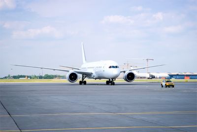
In addition, many aerospace designers use composites in their design for any structure that is not impact bearing, such as landing gear or the lower frame. Many other structures in the aircraft, including beams, shelves and skin, can be made of composite panels. As an example, the recent Boeing 787 design is constructed of more than 50% composite materials.
However, composites can be exceedingly difficult to simulate, usually requiring multiple simulation tools to solve and model composite layers and properties.
How can design engineers simulate composites successfully in the quickest amount of time and with the most accuracy?
Sharing Models Across Platforms
Ansys has teamed up with various software vendors to provide a complete workflow for composite manufacturing, design and analysis. For example, Ansys Composite PrepPost (ACP) works with the HDF5 Composite CAE interface to provide a user-friendly and fast workflow for design engineers using AniForm, CADWIND, 9T Labs and Hexagon solutions. The HDF5 interface is a vendor independent exchange format. Using the interface, designers can experience a greater degree of innovation, faster time to market and an easier, more accessible design workflow.
Through the HDF5 interface, users can transfer their composite layup data to and from ACP to complete and speed up the entire computer-aided engineering chain from modeling the manufacturing process to simulating the performance in operation. Combining these products allows engineers to design across platforms, easily collaborate and use the simulation tools that they are familiar with all in one place.
The ACP and AniForm Workflow
One of the first steps when simulating composite models is to account for manufacturing effects, such as material shear, and changes in the fiber directions and thickness. This is required because these properties significantly affect the equivalent part stiffness, which in the end affects the net part weight.
For thin-walled, shell-like composite parts, the composite forming processing technique is frequently used. The AniForm Suite simulation software is the state-of-the art solution for accurate composite forming predictions. Within the scope of optimization, numerous tooling and handling concepts can be studied with the software. For example, engineers can consider both rigid molds and flexible membranes.
Using the HDF5 interface, AniForm can export new composite layup information that was discovered during forming and then transfer it for analysis in Ansys. Therefore, the initial state and material properties of the composite in ACP can be described more accurately, which improves the quality of the structural simulations. The goal is to show the entire process chain from press molding simulation in AniForm to structural simulation in ACP.
The ACP and CADWIND Workflow
Composite pressure vessels are a common solution for storing gases and liquids at high pressures. Their lightweight design is beneficial to a wide range of applications in the automotive, aerospace and mobility industries, among others.
Pressure vessels are typically manufactured with a filament winding process. Composite filaments or tapes are wound at different angles around a rotating liner. The lay-up design of the pressure vessel is dictated in many parts by the process. On certain geometric features, like vessel domes, the composite filaments overlap in some regions more than others and their angles of orientation and mechanical properties vary. CADWIND simulates the filament winding process and generates machine codes for an automated laying. Then, ACP finite element models (FEMs) can be used to analyze the structural response to internal pressures, impacts and other loading conditions, taking into account the complexities of the layup.
The ACP and 9T Labs Workflow
Continuous fiber 3D printing has introduced a paradigm change in the way thermoplastic composite parts are designed and manufactured. 9T Labs offers Fibrify, a software integrated into SpaceClaim, which enables users to design composite parts with total freedom in fiber placement across the part and, at a later stage, control the additive manufacturing hardware in real time.
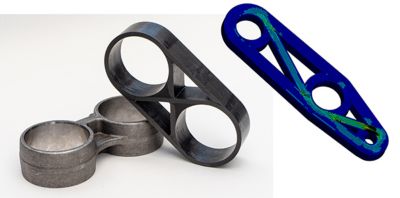
Fibrify supports the exportation of files directly to Ansys ACP, so that the user can run finite element simulations and consequently optimize the fiber placement against the exerted loads. The data transfer is enabled through the HDF5 interface, and as such, the entire CAE chain from design to finite element simulation and manufacturing, is closed without the need to interpret design data.
The ACP and Hexagon Workflow
One challenge of composite material simulation is achieving an accurate depiction of its formulation. Unlike a conventional material such as steel, a composite is a made with fabrics of fibrous materials that are layered at different orientations to make a single material. A single model, then, could require dozens, hundreds or even thousands of layers, or “plies.”
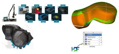
Hexagon’s Vision System 3D is an optical scanner and software tool that can help engineers overcome this challenge. The Vision System 3D accurately depicts composite materials in a simulation by scanning and digitizing fiber orientations of semi-finished carbon composite parts through detailed surface texture mapping. Combined with 3D modeling data, the Hexagon software delivers a 3D fiber orientation measurement for comparison with simulation or design data to detect, document and classify previously difficult-to-define production errors.
In addition, the Hexagon software can export this information in HDF5 format which can be imported and mapped seamlessly on a finite element mesh through the HDF5 interface and then tested for failure risks.
By partnering with leading vendors and using the HDF5 interface, Ansys and its partners hope to provide the solutions design engineers need to develop their products quickly, accurately and with a robust workflow.
A special thanks to our partners for the collaboration and use cases:


