-
United States -
United Kingdom -
India -
France -
Deutschland -
Italia -
日本 -
대한민국 -
中国 -
台灣
-
Ansysは、シミュレーションエンジニアリングソフトウェアを学生に無償で提供することで、未来を拓く学生たちの助けとなることを目指しています。
-
Ansysは、シミュレーションエンジニアリングソフトウェアを学生に無償で提供することで、未来を拓く学生たちの助けとなることを目指しています。
-
Ansysは、シミュレーションエンジニアリングソフトウェアを学生に無償で提供することで、未来を拓く学生たちの助けとなることを目指しています。
ANSYS BLOG
September 21, 2023
Ansys HFSS 2023 R2 Unleashes an Array of Improvements
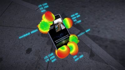
When most of us turn on our cell phones, we’re primarily focused on the calls we’ve missed, the texts we’ve received, and how much battery life is left rather than the radio signals that make our communications come to life. However, antenna simulation is critical to all of these interactions, as cell phone antennas radiate and capture the signals that make them possible.
5G multiple-input/multiple-output (MIMO) antennas and their supporting systems can be found deployed on conventional towers or, depending on the environment, on other infrastructure, such as on the side of a building. These structures or platforms can impact antenna behavior significantly, which contributes to poor signal quality. Using simulation techniques enables engineers to understand and optimize the performance of these arrays in various environments so we can hear each other.

Simulating smartphone antennas
Ansys HFSS is a multipurpose, full-wave 3D electromagnetic (EM) simulation software for designing and simulating high-frequency electronic products such as antennas, antenna arrays, radio frequency (RF) or microwave components, high-speed interconnects, filters, connectors, integrated-circuit (IC) packages, and printed circuit boards (PCBs). Engineers worldwide use HFSS software to design high-frequency, high-speed electronics found in communications systems, advanced driver assistance systems (ADAS), satellites, and Internet of things (IoT) products.
Users have come to rely on HFSS capabilities such as Mesh Fusion, which enables the electromagnetic simulation of complex designs by applying targeted meshing technologies to drill down on a higher level of geometric complexity without compromising accuracy and reliability. Through HFSS and its multitude of computational electromagnetics solvers, system designers can optimize antenna placement, fix signal integrity issues such as electromagnetic interference/co-site interference, and more. And, as a part of the Ansys complete PCB design solution, HFSS also facilitates component simulations at the board, circuit, and package level.
This year Ansys is once again expanding HFSS capabilities by adding new functionality to the HFSS 3D Layout workflow, extending the simulation of arrays, and increasing computing power that leads to faster simulations.

Ansys Q3D Extractor and Ansys RaptorX Now Integrated into Ansys HFSS 3D Layout
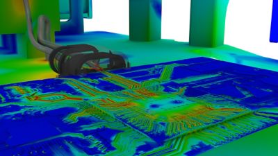
Integrating Ansys Q3D Extractor and RaptorX solver technologies with HFSS 3D Layout gives engineers a complete electromagnetic simulation and modeling solution for IC design. Within HFSS 3D Layout, it is now possible to combine the electromagnetic capture of a full chip design with Q3D resistance, inductance, capacitance, and conductance (RLCG) parasitics at both the package and board level to execute a full chip-to-system EM simulation.
This integration isn’t expanding IC simulation insomuch as it is expanding the technologies used for IC simulations. Both solver technologies are being added to the optimized workflow for HFSS for PCBs and packaged ICs. Their unique capabilities complement each other to further enhance the HFSS workflow.
Specifically, Q3D can extract models that are very effective for power integrity and analyzing power delivery networks in general. This year the addition of Q3D came organically, as there has been a natural demand for the same Q3D solver technology in similar optimized layout workflows like HFSS 3D Layout.
Conversely, RaptorX, while lacking some of the features of HFSS (such as the ability to look at electromagnetic fields, for example), is very performant for IC design. By integrating Raptor X into the existing 3D Layout workflow, engineers can take advantage of its powerful optimization engine to do design of experiments (DOE), parametric analysis, and optimization.
Simulation Capabilities Expand to 3D Component Arrays with Platform Geometries
When we talk about simulating 3D component arrays with platform geometries, we’re referring to improvements to simulation of antennas on or in a larger structure such as an airframe or cell tower — a capability that further reinforces HFSS’ reputation of being able to execute EM simulations over scale with gold-standard accuracy. Previously, those array designs could only be simulated in isolation, whereas now they can be simulated on a platform, expanding the application space for 3D component array technology.
With this change, HFSS is an even more powerful tool for simulating antenna arrays, using techniques common to radar and communication system designs such as 5G and 6G communication systems. Now engineers can put arrays on a platform, such as an air frame of an aircraft or a cell tower, as they are applied to 5G/6G applications. This further expands the application space for related 3D component array technology.
Distributed Compute for Adaptive Refinement Speeds Simulation Performance
Adding HPC scalable distributed adaptive refinement (beta) to HFSS helps extend the software’s overall performance through efficient utilization of distributed computing resources. The end effect of this refinement is improved simulation performance in the areas of speed and efficiency, which further parallelizes the adaptive meshing process.
Using HFSS, for example, engineers can realize as much as an 8X speedup in simulation, which, by further distributing the design, parallelizes the adaptive meshing process across multiple compute cores at the geometric level. The end result of higher parallelization is better scalability that leads to faster, better performance.
Of course, the software has more great features to explore. Discover how Ansys HFSS can help you design and simulate high-frequency electronic products quickly, accurately, and efficiently.


