-
United States -
United Kingdom -
India -
France -
Deutschland -
Italia -
日本 -
대한민국 -
中国 -
台灣
-
Ansysは、シミュレーションエンジニアリングソフトウェアを学生に無償で提供することで、未来を拓く学生たちの助けとなることを目指しています。
-
Ansysは、シミュレーションエンジニアリングソフトウェアを学生に無償で提供することで、未来を拓く学生たちの助けとなることを目指しています。
-
Ansysは、シミュレーションエンジニアリングソフトウェアを学生に無償で提供することで、未来を拓く学生たちの助けとなることを目指しています。
ANSYS BLOG
April 26, 2018
Electric Transformer Design with Ansys Discovery AIM
Transformers are used extensively in electronics products to modify voltage before electrical energy can be transmitted. Alternating current in one coil produces a varying magnetic field that induces electromotive force, allowing power to be transferred from one coil to another through a magnetic field without metallic connection.
Designing these electronics systems is an art of maximizing or minimizing induction depending on the requirements of the circuit. Computational electromagnetics can confirm good coil proximity and sizing in systems where maximal inductance is required, such as in the case of a shared iron core within an electric transformer. Alternatively, it is desirable to identify stray flux leakage when inductance is unwanted, such as between a circuit coil and metal framing used in a housing. Current is needed to drive through the coil, but you also don't want the electromagnetic effects to be inducted within the framing and, as a result, generate undesirable heat or reduce the efficiency of the system.
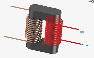
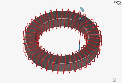
Ideal transformer coils with shared ferrite core (top) and toroidal transformer coil with ferrite core (bottom), as modeled in Ansys Discovery AIM.
Ansys Discovery AIM excels at modeling ideal and toroidal transformers. Results from these simulations can be used to maximize electric transformer performance, and indicate regions where electromagnetic screenage/shielding may be needed within a circuit. For an ideal electric transformer, this might involve looking at improvements in inductance by adding a shared ferrite core within the circuit.
Weak mutual inductance illustrated by magnetic field for transformer with no ferrite core.
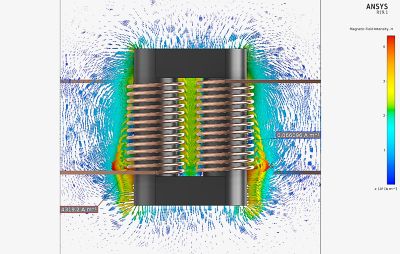
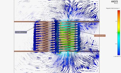
Strong mutual inductance illustrated by magnetic field for electric transformer with ferrite core.
Strong mutual inductance demonstrated by coils with similar currents in transformer with ferrite core.
Discovery AIM’s functionality really shines in its ability to model true coil geometries, in addition to coils approximated as cylinders. For a true coil geometry, you see the realistic distribution of magnetic effects between and around coil turns, with air modeled within and around the wiring. For toroidal transformers, it creates magnetic fields that are intended to remain contained inside the core, so they require less electromagnetic screenage, making them ideal for concentrated environments.
Discovery AIM can evaluate the magnetic flux inside toroidal transformers, and point out areas where leakage may be a concern. These results are substantiated by Discovery AIM’s advanced electromagnetic adaptive meshing capabilities, which automatically optimize meshing in regions of high electromagnetic effect. The meshing functionality is automated and physics-sensitive, and offers customizable tool options for skin depth resolution, core loss and eddy effect computation.
Toroid magnetic flux contained within ferrite core analyzed with Discovery AIM.
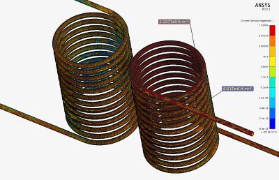
Mesh and current density is shown for transformer with no ferrite core.
Learn More
To learn more about the electromagnetic, as well as fluid, structural and thermal simulation capabilities in Ansys Discovery AIM, we invite you to test drive it for 30 days free of charge. Also, be sure to download an example file and optimize your own transformer.


?)
