


TOPIC DETAILS
What is Laminar Flow?
Laminar flow, also called streamline flow, is a flow regime in which the particles in a fluid move in smooth, parallel layers. Minimal mixing occurs between adjacent layers, and any fluctuations that do occur are nonchaotic. Laminar flow exists when the viscous forces in fluid flow dominate the internal kinetic forces. This is unlike turbulent flow, in which irregular and chaotic movement of the fluid particles occurs, as seen in the swirls and eddies that develop. Laminar flow is most common in viscous fluids flowing at a relatively low flow rate.
Engineers care about laminar flow because the lack of mixing and relatively stable movement of the fluid impacts the loads on the solid objects a fluid is flowing around, the mixing that occurs in the fluid, and heat transfer. Sometimes engineers work to keep flow conditions laminar, as in an operating room, where you want laminar airflow to move contaminants away from the patient. Or a design may benefit from creating turbulent flow, as in a golf ball, in which laminar flow increases drag.
How is Laminar Flow Calculated and Characterized?
Because of the streamlined, layered nature of laminar flow, engineers use equations to calculate the fluid velocity, velocity fluctuations, and pressure fluctuations caused by turbulent flow. This characterization starts with the dimensionless quantity called the Reynolds number. Further equations then capture other behaviors helpful in designing for or measuring laminar flow.
Predicting Laminar Flow: Reynolds Numbers
The British researcher Osborne Reynolds published a paper in 1883 describing the transition from laminar to turbulent flow in water flow in simple pipes. His observations showed how the ratio between internal and viscous forces predicts how likely it is for turbulence to occur. This dimensionless value is referred to as the Reynolds number.
The equation for the Reynolds number is:
ρ = Density of the fluid (kg/m3)
u = Flow velocity (m/s)
L = Characteristic dimension or characteristic length, such as pipe diameter, hydraulic diameter, equivalent diameter, chord length of an airfoil (m)
μ = Dynamic viscosity of the fluid (Pa·s)
v = Kinematic viscosity (m2/s)
Reynolds’ work showed that pipe flows with a low Reynolds number stays as laminar flow because they lack the kinetic energy needed, in the form of inertial forces, to convert any instabilities in the fluid motion into flow perpendicular to the mean flow direction. Then turbulence is more likely, as the velocity of the fluid or density increases relative to the viscosity of the fluid.
Important Characteristics of Laminar Flow
When dealing with laminar flow, some additional characteristics that engineers, physicists, and chemists pay attention to are:
Boundary Layer
The boundary layer is the layer of flow against a solid surface. If the type of flow is laminar, the flow remains parallel to the surface in the boundary layer. The fluid has zero velocity at the surface, referred to as a no-slip boundary condition, and the velocity increases monotonically away from the surface until it achieves the bulk fluid velocity. A boundary layer can be laminar or turbulent. The thickness and velocity profile of the boundary layer is an important characteristic in determining drag on and heat transfer to the surface.

An example of a computational fluid dynamics (CFD) simulation of laminar flow in a volume with a moving flat plate. The relative velocity is zero against the plate surface and monotonically increases to the bulk velocity.
Diffusion
Unlike turbulent flow, in which cross currents and eddies dominate mixing between fluid layers, the streamlined flow pattern of laminar flow keeps particles in one layer of flow separated from other layers, and mixing occurs through diffusion between adjacent layers. Diffusion is the movement of a material from a high concentration to a low concentration. Therefore, in laminar flow, particles move from a layer with high concentrations of a given substance to adjacent layers with a lower concentration.
Surface Roughness
Surface roughness is a parameter engineers can control when designing to keep or disrupt laminar flow. The rougher a surface, the greater the friction drag in the boundary layer, and if the shear stresses grow enough to overcome the viscous forces, the flow will transition from laminar to turbulent. A great example of this is in the design of turbine engine compressor blades, in which the roughness of the metal surface can greatly impact the development of a turbulent boundary layer, thus impacting the performance of the blade.
Velocity Profile
Because laminar flow is not chaotic, you can create a clear picture of how the velocity varies across the direction of flow. This is called a velocity profile. A velocity profile is a simple way to see where high velocities and low velocities exist and, when changes are made to geometry or inlets, how velocity is impacted.
How is Laminar Flow Modeled?
Because fluid flows in parallel layers in laminar flow, the behavior of fluids in a laminar flow regime can be calculated using the governing equations of fluid dynamics, the Navier-Stokes equations. These equations define the conservation of mass, momentum, and energy to describe the pressure and velocity of a fluid. Simple flow in a cylindrical pipe or between two plates can be characterized using closed-form solutions. But flow in and around more complicated shapes uses computational fluid dynamics (CFD) to discretize the flow volume and then solve for pressure, velocity, and temperature over time.
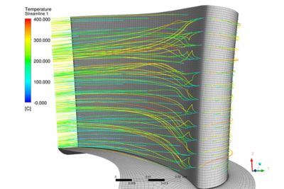
A CFD model showing laminar flow around a turbine engine blade
Because laminar flow follows the shape of the bounding surface, one key to successful modeling of laminar flow is to create a mesh, the discretization step, that is parallel to that surface to best capture the boundary layer. Engineers often use a tool like Ansys TurboGrid™ turbine blade meshing software to automatically create efficient and accurate boundary layer meshes for known topologies.
Since the CFD program solves for the flow in each cell in the model, any distortions for a uniform shape or abrupt cell size changes can introduce numerical errors into the solution. Engineers building CFD models spend time during mesh creation making sure that their meshes are well behaved and also efficient. This is because the number of cells determines the runtime. It’s important to have a tool like Ansys Fluent® fluid simulation software that includes meshing capabilities that help users create efficient mesh topologies, leading to accurate and efficient solutions.
A lot of the work in modeling laminar flow comes from trying to determine when the flow turns turbulent. Modeling turbulent flow requires additional mathematical models beyond solving for the standard Navier-Stokes equations. So, even if your goal is to keep your flow laminar throughout the geometry you’re modeling, you may need to include some turbulence modeling.
One change in the world of laminar flow modeling in the past decade is the use of graphics processing units (GPUs) to solve CFD models. One or more of these computational accelerators can greatly reduce the run time of a given model, allowing engineers to conduct CFD solves on relatively inexpensive workstations or getting more iterations on a design done in the same amount of time.
Why is Understanding Laminar Flow So Important?
Regardless of the type of fluid you’re working with, from flow in pipes to aerodynamics for aircraft, understanding and properly predicting laminar flow can be a significant part of designing products, from nuclear power plants to the latest high-performance aircraft. As mentioned above, understanding laminar flow is often about understanding what range of Reynolds numbers, for the application you’re working on, results in a transition in your flow field from laminar to turbulent flow.
A simple example is a laminar flow hood in a laboratory. These are boxes in which scientists and technicians can work on hazardous materials, knowing that the straight-line flow of air into the hood and up the vent will keep them safe. Or you can take the golf ball example, in which you want to introduce turbulence as soon as possible to reduce drag.
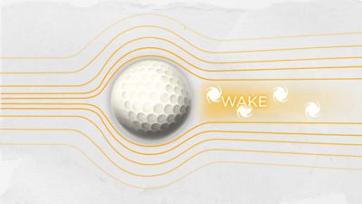
An illustration of how dimples on a golf ball are used to introduce turbulence that keeps the flow attached to the back side of the ball, reducing the size of the wake and, therefore, drag on the ball
Laminar flow is also important when transporting multiple materials in a fluid without much mixing occurring, frequently with the intention of depositing the transported material somewhere. In semiconductor manufacturing, engineers designing chemical vapor deposition chambers work to achieve uniform laminar flow into the chamber and over the wafer, in order to achieve a uniform deposition of the chemical they’re working with.