


ANSYS 部落格
February 15, 2024
Infinitum:專為更有效率且永續發展的未來所設計的馬達
有數十億個電動馬達在驅動世界運轉,總共消耗超過一半的全球電力,其中大部分來自排放量高的燃煤發電廠。因此,任何馬達效率的改善都會大幅促進全球脫碳,並加速電動車轉型。
在這方面,位於德州的製造商 Infinitum 開發出比傳統鐵芯馬達更輕、耗能更少且排放量更低的新一代馬達。
他們透過 Ansys 新創公司計畫取得 Ansys Fluent 和 Ansys Maxwell 軟體,在這些軟體的協助下成功完成開發。Infinitum 公司表示,與相同輸出功率的傳統馬達相比,其產品組合中使用空芯技術製造的馬達尺寸小 50%、重量輕 50%、製造時的碳排放量減少近 20%,而且效率提高 10%。
減少重量並降低排放量
印刷電路板 (PCB) 定子技術是造就空芯技術差異的核心。
定子是電動馬達中的固定組件,採用交流電時會產生旋轉磁場。大多數的定子都是由疊層的鐵芯和絕緣線圈組成 (通常為銅),稱為繞組。
在一世紀前發明電動機以來,便已開始使用鐵芯,但這並不代表鐵芯十全十美。其中一個缺點就是鐵芯很重,而且開採鐵礦並非最環保的流程。
鐵芯定子容易出現效能問題,最顯著的是鐵損 (與引發的渦電流和磁滯相關的能量損失) 以及轉矩漣波 (轉矩輸出的週期性變化) 和齒槽效應 (導致運動顫動的非期望轉矩元件)。
Infinitum 透過從定子中移除鐵芯和銅繞組,並替換為專利的 PCB 定子,增加馬達的效能尺寸比、減輕重量、減少轉矩漣波和齒槽效應的影響,並抑制渦電流損失。在這個設計中,磁通量在兩個轉子之間傳遞,路徑中沒有鐵芯,因此稱為空芯。減少鐵和銅的使用量 (雖然在定子中仍然需要銅繞組),等於減少資源使用量並降低採礦造成的負面影響。綜合起來,這代表製造馬達的碳排放量可以減少將近 20%。
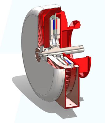
高效率的輕量交流發電機渲染
將損失量化
因為渦電流會產生熱能,即浪費掉的能量,導致效率降低,因此必須在馬達、發電機和變壓器中將熱能降至最低。當 Infinitum 開始開發 PCB 定子時,其內部設計工具計算出渦電流損耗將高達 126 瓦 (W)。然而,測試顯示的損耗卻顯著增加至 330 W。為了調查此落差,工程師轉而採用 Maxwell。
Infinitum 的工程師考慮到渦電流是在最接近磁性轉變的位置產生,因而使用 Maxwell 檢查簡化的定子模型,專注於單一銅線圈的直線股與移動的磁鐵之間的相互作用,而磁鐵移動速度不影響完整規模定子的傳真度。
Maxwell 的模擬釐清渦電流主要侷限於最靠近磁性轉變的三個中心線圈股上,並且進一步受到線圈和磁鐵之間氣隙大小的影響。藉由推估完整定子中所有線圈的模擬結果,Infinitum 工程師確定,線圈中相鄰股之間的鄰近效應導致設計與現實之間的差異。
透過解決 PCB 定子模型與測試之間的差異,Infinitum 的工程團隊能夠調整其內部設計工具使用的封閉解,使未來的測試更接近模擬所達到的結果。
順勢而為
任何馬達製造商都必須考量熱傳遞、熱損失和冷卻等因素,然而當產品體積小但功能強大,風險就會更高。Infinitum 使用 Fluent 進行熱管理模擬,包括為客戶設計客製化的空芯產品時。
最近,某家一流的建築與採礦設備公司要求 Infinitum 開發高效率且輕量的空芯交流發電機原型,可與現有發電機整合,提供 20 千伏安 (kVA) 的電力,並以每分鐘迴轉 1,500 次 (RPM) 的速率運作。
Infinitum 的工程師使用自家系統對初步機械設計進行建模並滿足專案的電力和介面要求後,轉而使用 Fluent 改良第一次迭代的空氣冷卻系統。
Infinitum 以均勻定子溫度和高效率為主要目標,致力於製作設計,使其透過內部空氣循環和內建機械驅動葉輪的流量來產生必要的冷卻功能。工程師也評估新開發具有扇形接觸區域的定子外殼壁傳導冷卻能力,這種設計旨在透過傳導提供更一致的冷卻效果,而非藉由均勻但較薄的接觸區域達成。

外殼溫度圖 (左) 和定子溫度圖 (右)
雖然 Fluent 模擬顯示客製化流程初期的定子溫度為可接受的低溫,但根據先前的 Infinitum 徑向葉片設計的初代葉輪概念,因風阻損失而造成效率下降幅度超出接受範圍。第一代葉輪具有 12 個葉片、390 毫米 (mm) 的外徑和 42 mm 的深度,每分鐘可產生 700 立方英尺 (CFM) 的流量。工程師移除四個葉片、將外徑縮小到 290 mm、深度縮小到 30 mm 後,模擬顯示流量下降到更有效率的 300 CFM。這個中間葉輪在冷卻系統的後續兩個迭代中發揮了作用。
外殼鰭片的配置和數量也證實是這個系統成功的關鍵。在工程師修改葉輪之後,雖然定子溫度保持在預期範圍內,但交流發電機外殼的驅動端和非驅動端之間仍有顯著的溫差。工程師得出的結論是,由於驅動端外殼缺乏內部鰭片,導致冷卻不對稱。為外殼設計增加內部鰭片後執行模擬,顯示定子和外殼的溫度梯度較低也更均勻。
流量研究結果證實外殼壁的扇形特徵透過傳導成功去除 28% 的定子熱能,設計師也在外殼圓周添加鰭片,以進一步提升散熱效率。這次迭代還發現外部護罩側面將空氣引導至外殼鰭片的效果不佳,並且現有的下部安裝特徵對部分鰭片造成二次氣流阻礙。進一步的模擬確認修改護罩側面以遵循鰭片輪廓,並減少安裝特徵的大小,便可解決這些問題。
為了完成內部驅動流量的葉輪設計並確定建議的外部流量,Infinitum 使用 Ansys CFX 和簡化的冷卻系統機械模型,進行質量流量需求研究。
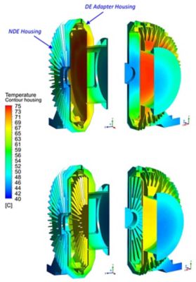
沒有內部鰭片的外殼溫度 (上) 和具有內部鰭片的外殼內部溫度 (下)
在這個質量流量模擬模型上,電源連接頭和安裝座被移除,並以基於計算流體動力學 (CFD) 結果改良的護罩取代現有的護罩固定配件,將空氣引導至交流發電機外殼上方。根據鑄造供應商的規格,外殼材料改為灰鑄鐵,鰭片厚度設定為 6 mm,基本壁厚設定為 10 mm。在內部轉子運動設定為 1500 RPM 的情況下,外部流量在 100 到 400 CFM 之間變動,熱負荷則在 100% 到 130% 之間變動。
Infinitum 藉由繪製和推估定子溫度與外部氣流曲線以及系統阻抗曲線,確定其設計的最小操作點和建議操作範圍。根據這些發現,他們開發一款流量為 300 CFM 的葉輪,並使用 3D 列印製作原型。
尖端模擬軟體的建模和測試能力,使設計師和工程師能夠不受實體模型的多項時間和財務限制影響,對無數的變化進行實驗。在這些優勢的幫助下,Infinitum 成功進入仍處於起步階段的專業市場,這應該可以證明數位工程的價值。Infinitum 的例子證明,即使是在數世代以來沒有顯著技術進展的產業中,也能掀起波瀾,並為解決世界上一些最棘手的問題開闢道路。
進一步瞭解 Ansys 新創公司計畫,檢視資格要求、軟體套件及成功案例。