-
United States -
United Kingdom -
India -
France -
Deutschland -
Italia -
日本 -
대한민국 -
中国 -
台灣
-
-
產品系列
查看所有產品Ansys致力於為當今的學生打下成功的基礎,通過向學生提供免費的模擬工程軟體。
-
ANSYS BLOG
September 7, 2021
How to Improve Turbomachinery Durability with Aeromechanics Simulation
Designing efficient, lightweight and reliable turbomachinery is challenging. Pushing efficiency to new limits results in higher operating temperatures, while reduced blade weight and thickness must still meet stress and vibration criteria.
Slender blade designs in harsh environments are prone to fatigue and fracture. Miscalculations, even in the smallest degree, result in extremely high maintenance and downtime costs or complete failure, jeopardizing safety of flight.
On the other hand, accurate performance prediction ensures durability, which enables designs to push limits.
Ansys offers streamlined, advanced aeromechanical workflows to analyze all fluid and structural interactions to ensure new materials and designs are not susceptible to failure.
Aeromechanical Workflows
Aeromechanical analyses are fundamentally expensive, transient multiphysics, fluid-structure interaction problems. When simulating these problems, you need accurate and efficient data transfer between solvers. That is why Ansys developed a practical workflow, with the best-in-class solvers, for these applications.
Whether performing a blade flutter or high cycle fatigue (HCF) forced response analysis, Ansys has an efficient and practical one-way coupling solution with advanced mapping tools to ensure accurate data transfer.
Blade Flutter Analysis
To ensure the aerodynamic loads will damp out the blade vibration at natural frequencies, you need to start with a one-way coupled blade flutter analysis.
A pre-stressed modal analysis is performed in Ansys Mechanical. Mechanical automatically maps the mode shapes onto the blade in the computational fluid dynamics (CFD) setup and performs an unsteady simulation. This uses the Harmonic Analysis method to simulate blade flutter in the frequency domain and is significantly faster than a traditional time marching transient analysis. CFD solutions for a range of mode shapes, frequencies, amplitudes and nodal diameters are obtained. These results can be examined for stability with a performance map to show which areas of the blade are fluttering.
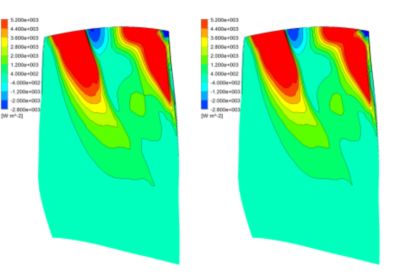
For a deeper analysis, you can examine wall power density to find exactly which areas are positively and negatively contributing to the damping. Finding these critical areas on the blade creates a more robust design.
The aerodynamic damping values obtained from the blade flutter analysis can be used in a forced response analysis.
Forced Response Analysis
Blade displacements and stresses are computed by performing a one-way coupling simulation. Finding where the natural frequency will be excited at different engine orders can be obtained from a Campbell Diagram.
The forcing function at engine orders of interest can be simulated in an unsteady CFD simulation on a “hot geometry,” which describes when the turbine is running at full speed and temperature, to calculate the pressures on the inlet guide vanes (IGV) and stator blade surfaces.
These pressure values, along with the engine order and rotation speed, are automatically imported and mapped to the structural mesh as a load in Ansys Mechanical. Once the simulation is run and results are obtained, an interference diagram shows where modal ranges and harmonic indexes cross, causing a forced response.


