-
United States -
United Kingdom -
India -
France -
Deutschland -
Italia -
日本 -
대한민국 -
中国 -
台灣
-
-
產品系列
查看所有產品Ansys致力於為當今的學生打下成功的基礎,通過向學生提供免費的模擬工程軟體。
-
ANSYS BLOG
December 06, 2019
FEA Identifies Microvias and PTHs at Risk of Fatigue Failure
Plated through hole (PTH) and microvias are structures that connect signal circuits at different layers of a printed circuit board (PCB). The demand to increase the density of these interconnects has increased significantly over the past decade due to trends toward higher input/output (I/O) densities and smaller electronic packages. The challenge is that these structures are one of the most common causes of fatigue failure in PCBs.
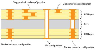
Interconnect microvia configurations in a PCB
One advantage of microvias is that they can be placed in different locations between the layers of the PCB. This means that they can be in isolated, staggered, stacked or continuous positions in the copper layers of the chip. When the interconnects are staggered, they tend to have better reliability than when they are stacked. However, both configurations have better reliability than traditional PTHs.
Reliability concerns complicate the electronics industry’s ability to map interconnects. As result, reliability engineers are tasked to develop models that can predict fatigue failures of these systems.
Using finite element analysis (FEA), engineers can analyze the reliability of PCBs that utilize microvias or PTHs.
How Simulation Can Determine PCB Reliability
A major reliability challenge stems from the copper coatings of microvias and PTHs. The different coefficients of thermal expansion between the metal and other PCB materials could lead to fatigue.
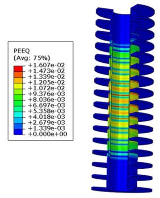
Engineers can use FEA to predict the number of cycles until PCBs experience failure. First, they can average the equivalent plastic strain for every element along the z-axis of a PTH.
The next step is to compute the strain for the elements within the PCB. The strain values can be input into the Coffin-Manson equation to estimate the number of cycles to failure.
A contour of equivalent plastic strain in a PTH that features 12 layers and a thermal cyclic loading of 25C (77F) to 150C (302F).
Next, multiple experiments can be conducted to validate the FEA results and predictions. In-house tests showed that the FEA results for all PTH configurations strongly correlated with experimental results.
Manufacturability Analyses Are Needed to Determine Microvia Reliability
Manufacturability analyses need to be performed to successfully predict the number of cycles to fatigue failure.
Manufacturability analyses for stacked and single microvias predict the likelihood of interfacial separation during the reflow soldering process.
The separation between microvia bodies and PCB pads occur due to high tensile stress during the solder reflow process. Experiments and material properties are needed to determine the tensile stress ranges.
Engineers need to understand the PCB manufacturing process to determine its reliability.
In theory, microvia structures can withstand stresses up to copper’s strength. However, microvias fail at much lower stress due to manufacturing defects. Therefore, it’s best to perform an industry literature review to determine empirical data on copper’s critical stress values.
Ansys Sherlock Automated Design Workflow for Fatigue Failure
Engineers can use the Ansys Sherlock automated design analysis to predict the probability of fatigue failure for PCB designs with thousands of interconnect structures.
The workflow provides tools that can identify reliability concerns when developing PCBs, microvias and PTHs.
For instance, Sherlock can be used to assess how mismatching coefficients of thermal expansion will affect a product over its entire lifecycle.
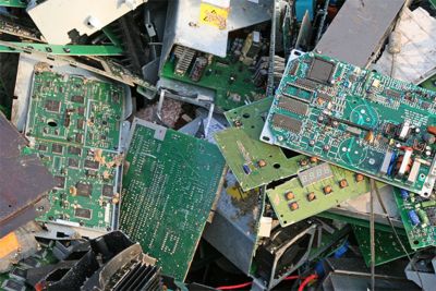
ANSYS Sherlock can help prevent electronics from going into the dump before their warranty is up.
After identifying areas of concern, engineers can address those challenges proactively before sinking resources into expensive prototypes.


