-
United States -
United Kingdom -
India -
France -
Deutschland -
Italia -
日本 -
대한민국 -
中国 -
台灣
-
-
產品系列
查看所有產品Ansys致力於為當今的學生打下成功的基礎,通過向學生提供免費的模擬工程軟體。
-
Ansys Blog
March 7, 2017
Pipe Simulation Using Ansys: A Quick Introduction
Pipe exist everywhere. There are a wide range of applications involving pipes. For daily life, pipes are used in the water line for our house, the air conditioner of the car we are driving, and in the gas station where the gasoline and diesel are transported. Industry-wise, a lot of pipes are used for processing, gas and liquid transmission, transmission as well as extensively in power plants.
From a structural analysis point of view, a pipe is a slender structure with a tubular cross section that could be very long along the length direction. A beam can also have tubular structure, but most beams or columns are used for strength purposes. The dominant function of the pipe is used for transporting fluids and gases. The liquid/gas transporting could be hot, under high pressure, and also be viscous. We want to use a minimum pipe thickness to save material while still satisfying the temperature and pressure requirements.
Engineers whose main focus is designing piping systems typically rely on specialized analysis tools. Those niche tools have streamlined the process from creation of piping system geometry to final output per industry code. They are efficient for everyday pipe designers. However, for a structural design engineer who comes across piping structures or the piping geometry is relatively simple. Those specialized tools could be overkill. Also, there are observed limitations in those tools when it comes down to more detailed or advanced analysis.
Ansys Mechanical, known as a general purpose finite element analysis program, provides a set of technologies and workflows that allows piping analysis to be an easy task. Some capabilities(contacts, detailed modeling, hybrid model) goes beyond what a typical piping software can do.
In this blog, I would like to give you a brief introduction into some technologies and features we have for piping analysis. To start with, let me introduce you three elements: namely pipe288, pipe289 and elbow290. Pipe288 is 3-D 2-node pipe, pipe289 is 2-D 3-node pipe, elbow290 is 3D 3-node elbow. Purely by name, you can tell that elbow elements are used for elbow (per piping terminology).
PIPE288 and PIPE289 can handle both thin-walled and thick-walled (even a solid circular) cross-sections. With the thick-walled option, a full 3D stress state is adopted.
PIPE288 and PIPE289 accept only circular cross-sections. The cross-section will remain circular during deformation (i.e., only uniform radial expansion is allowed). Therefore, PIPE288 and PIPE289 should only be used for straight pipe segments.
On the other hand, ELBOW290 allows for initially non-circular sections and accounts for general section deformation, including ovalization, warping, and non-uniform radial expansion. With these advanced capabilities, ELBOW290 is suitable for pipe bends and straight pipe segments that may undergo large section deformation (e.g., collapse of the section).
Pipe288/289 elements can account for added mass (internal fluid mass), hydrodynamic added mass(external fluid), wave loading and buoyant effects. Pipe to surface contact (like pipe-lay on seabed) and pipe-to-pipe contact (like PIP) can also be addressed.
Now let’s go through some of the basic features related to pipe analysis in Ansys Mechanical. Please be aware that Ansys Workbench Mechanical only exposes a subset of the features of the pipe capabilities, but you can always insert commands snippets or use MAPDL to explore full capabilities.
Geometry:
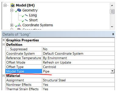
Starting with geometry, you need a “line body”(Ansys terminology) for pipe and assign tubular cross sections. If you build a geometry in Ansys pre-processing tools like Ansys SpaceClaim or DesignModeler, that is pretty straightforward. If your geometry has been pre-built in other tools, then you can bring them in Ansys SpaceClaim. If it comes in as just lines then you can simply create some cross sections and assign to them. If it comes in as volumes, you can take advantage of “Beam Extraction” tool to automatically convert a volume to a line plus cross section. Once you load the geometry in Ansys Mechanical specify “Model Type=Pipe”.
Meshing and Material:
Meshing and material specification is no different than if you are working on solid-based structures. You can also assign tabular temperature dependent properties (like stiffness).
Loading and Constraint:
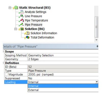
Internal and external pressure, Temperature. “Line Pressure” can be used to apply external loading (like overburden load).
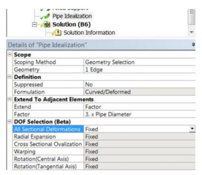
What does “Pipe Idealization” do? It is used to convert selected pipe elements to elbow elements, this is especially important for curved pipes. Since “Pipe Idealization” is using elbow290 element, which is a quadratic element at the solver level, please be sure to keep mid-side nodes when you are meshing.
Post-processing:
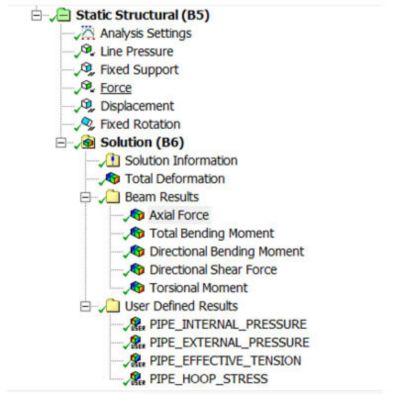
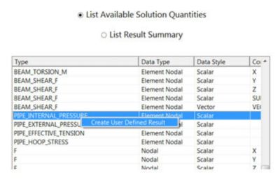
For common items like axial force, bending moment or shear force, these can be accessed through “Beam Results”. Additional output like hoop stress, internal/external pressure can be accessed using “Solution”->” Worksheet”->“ Create user defined result”.
You can use these results and do some result combinations, and compare with a pipe hand calculation spreadsheet. But we have something easy set up for you.
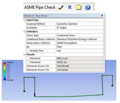
For those who are involved in gas transmission and distribution pipe systems, you will know ASME B31.8 well. For others, it is basically a requirement on how to process calculated stresses and compare that with code specified allowable. We have an Ansys ACT APP for that! Just go to Ansys App store and download an extension called ASME Pipe Check. It can save you some time. Here's a snapshot.
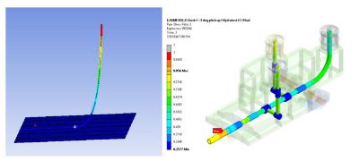
Lastly, I want to highlight a unique point about Ansys pipe simulation. I call it “Hybrid Model”. You can have combination of line, surface and volume structures in one system. In this way, you can study a bulk structures with some piping components, and interactions between pipe and other components. I am including a few snapshots using “hybrid model” here.
Learn what's new in Ansys Mechanical 2024 R1 by viewing our on-demand webinar.


