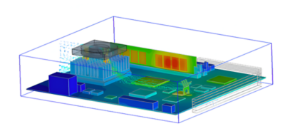
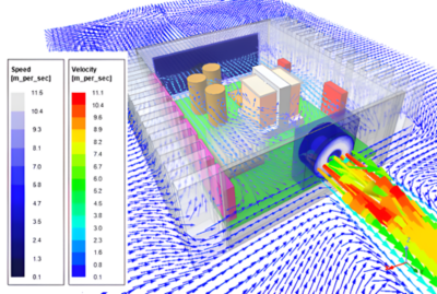
Electronics thermal management is an engineering discipline focused on efficiently managing heat in electronic devices and systems. It uses the physics of thermal conduction, convection, radiation, and thermodynamics to keep component temperatures within their acceptable operating range. If uncontrolled, temperatures will rise, component performance will drop, and some parts may fail. Also, connections between components and packages can weaken and break. Whenever you hear a fan blowing from your laptop or feel the heat on the back of your mobile phone, you experience thermal management.
Electronic devices work by moving electrical current through circuits and electronic components. Wires, PCB traces, connections, chip packages, and components all generate heat as current moves through the circuit. When the heat is not managed effectively, the temperature in each area of an electronic device climbs, changing material properties. Those property changes can create multiple problems, including increased resistance, lowered mechanical strength, signal distortion, and ultimately decreased product performance and a poor user experience. Materials also expand when heated and contract when cooled, putting stress on components that can lead to mechanical failure, fatigue, and premature aging of the component or system.
From mobile phones and electric vehicles to cooling CMOS cameras on satellites, thermal management plays an important role in the overall performance and robustness of today's electronics applications. That is why a comprehensive understanding of the options available is essential. Its application has become a critical part of product development and should be included in every step of the design process.
Before we discuss the particulars of managing excess heat, we should mention that the scale of an electronic system plays an essential role in the tools engineers can use to manage heat. Semiconductor chip packages present different heat generation and heat dissipation challenges than printed circuit boards (PCBs). Similarly, enclosures with multiple PCBs and other heat sources, such as power supplies, require solutions different from assemblies like racks or entire data centers. The classifications are chip-level, component-level, board-level, and system-level thermal management solutions.
Another important distinction is passive versus active thermal management. Electronics cooling approaches that do not use power are called passive cooling solutions. Active cooling solutions use power, usually electricity, to increase the velocity of convection fluids or to power a thermodynamic or thermoelectric device. Passive cooling is generally preferred because it uses no energy, has no moving parts, and is more cost-effective. Designs include active systems because passive cooling management schemes can never cool a device below the ambient temperature or when passive systems do not have the needed thermal performance.
Below is a list of the most common effective thermal management methodologies used today, divided into passive and active solutions.
Passive Thermal Management Methods
Thermal interface materials (TIMs): material between and around components used to insulate those components from high temperatures or to transfer heat away from heat sources. In potting and encapsulating, various acrylic, epoxy, silicone, and urethane resins coat or fully enclose a component, an assembly, or the whole device. Additional material types between components, including adhesives, gels, and greases, deliver high thermal conductivity between the elements.
Heat spreaders: an object that transfers heat away from a hot spot to a cooler location or to another thermal management solution. The geometry and material of a semiconductor package, a PCB, or an electronics enclosure moves thermal energy away from hot spots. At the package and board level, ball grid arrays, wires, vias, and ground planes are used. In enclosures, heat from boards and power electronics is directly transferred to the case or other heat management devices through fasteners and wedge locks.
Free convection: the most common and cost-effective cooling mechanism is the natural convection of air around a high-temperature object. Since hot air rises due to buoyancy, the thermal energy from a hot object moves into the air, then up and away from the part, pulling cooler air in to replace the warm air. Although air is the most common fluid in free convection, more demanding applications use other gasses and liquids.
Heat sinks: an object that is attached to a heat source and conducts heat away from the source object and then dissipates it through convective heat transfer to a fluid. The design of heat sinks maximizes the amount of surface area from which the convecting fluid can pull heat. Heat sinks are most commonly found on heat sources like CPUs, power electronics components, and lasers.
Heat pipes: A device that uses phase change in a volatile material to absorb thermal energy from a heat source. The energy converts the liquid into a vapor, and the vapor travels along the heat pipe to the other end, where the vapor condenses and returns to the hot end to repeat the cycle.
Infrared radiator: a large, flat metal plate using infrared radiation to transfer thermal energy away from the plate. Designs include radiators for applications in which there is no way to convect or conduct heat out of systems, usually in space.
Active Thermal Management Methods
Forced convection and forced air cooling: powered devices that use fans or blowers to create airflow over components or heat sinks. The higher velocity of the air increases the convective heat transfer and, therefore, pulls more heat from the object.
Liquid cooling: a thermal management method in which a liquid flows over a heat source to absorb heat and move heat away from the source for removal. Liquid cooling often uses forced convection or heat exchangers (e.g., radiators) to cool the liquid before it returns to the heat source. High-performance computers along with battery systems and electric motors and electric vehicles are common examples of using liquid cooling.
Jet impingement cooling: a highly efficient cooling solution that jets a fluid through a nozzle onto the heat source. The much higher velocities, turbulence, and sometimes vaporization at the impingement surface significantly increases thermal energy transfer from the object to the fluid.
Spray cooling: an approach similar to jet impingement cooling, but instead of a jet of fluid, a coolant is atomized into small droplets that vaporize when they strike the heat source. This phase transformation absorbs significantly more energy than convection.
Refrigeration: A vapor-compression thermodynamic cycle uses compression, condensation, expansion, and phase change to pull heat from a source. This approach is especially useful when the ambient temperature is well above the required operating temperature of the electronics. Data centers are a common example of refrigeration's use to cool the working fluids for free convection, forced convection, and liquid cooling systems.
Resistive heating: Most thermal management methods are designed to remove heat from an electronic system or component. However, in some applications, devices operate in extreme cold, and engineers need to include resistive heaters in their designs to raise temperature into an acceptable operating range. Resistive heaters are common in space-based electronics, some automotive electronics, and various Internet of Things (IoT) applications operating in extreme environments.
Thermoelectric cooling: a solid-state device that uses the Peltier effect to convert electrical energy into thermal energy. Current passes through two dissimilar semiconductor materials, causing the temperature on one side to increase and the temperature on the other side to decrease. This lower temperature side can be attached directly to an electronics component that requires cooling.
Engineers designing electronic systems, from a tiny microchip to a massive data center, must explore the system's thermal behavior and then choose thermal management solutions that meet the system’s thermal performance criteria, are cost-effective, and do not create issues with the system's electrical or mechanical requirements.
Designing for thermal management should be integrated into the overall product design process in general and the simulation-driven design process in particular. The following techniques allow the development team to understand the application, evaluate trade-offs quickly, and optimize a solution.
Component Characterization
An effective thermal management solution starts with knowing the thermal properties of the components going into the system. The design team should start with collecting technical information such as geometry, material properties, heat generation, heat capacity, standard operating conditions, and acceptable operating temperatures for every electronic and mechanical component in the system.
These values can be obtained from the supplier, or you may have to conduct thermal characterization testing. To estimate heat dissipation, electrical engineers typically run circuit models based on electrical behavior found in component datasheets. Simulation can also be used to determine allowable thermal strains in components and interconnects or to characterize the thermal behavior of an assembly of components.
Environment Evaluation
Once the team knows what is going on inside the electronic system, they need to understand the environment the system will operate in.
The options for thermal cooling in consumer electronics are fundamentally different from the thermal management options available in avionics.
Avoiding overheating in a smartphone is limited to what fits inside the case and the only place to dump heat is into the air around the device. An avionics package in a fighter jet has high-pressure, cooled air available to blow into an enclosure. Industrial IoT devices may not have access to cool ambient temperatures, chilled air, or water. The best solution for that application may be an onboard thermoelectric cooler. Similarly, standards and regulations in a given industry may determine which thermal management methodologies can be used.
Thermal Simulation
The wide variety of options and the tradeoff between competing requirements make simulation a perfect tool for developing a thermal management solution.
At the semiconductor chip package level, designers can iterate on the encapsulation approach, the location of thermal solder attachments and thermal vias, and the thickness of ground planes.
At the other end of the size spectrum, the flow of air in a data center in and around racks across an entire floor can be modeled and optimized with computational fluid dynamics (CFD).
Ansys Icepak® software is a great example of a CFD solution designed specifically for electronic cooling at the component, package, board, and enclosure levels. It allows engineers to import designs directly and quickly model thermal management solutions. At the chip level, engineers count on Ansys Redhawk-SC Electrothermal™ software as a signoff solution for 2.5D and 3D-IC systems. Redhawk-SC Electrothermal software connects with Icepak software to enable system-aware chip design.
Another source of heat that engineers need to manage is heat generated through the use of electromagnetics in electronics applications. High-frequency applications such as high-power antennas produce heat because of losses in the media the electromagnetic waves travel through. A tool like Ansys HFSS™ software can predict the amount of heat generated, which is then applied as a boundary condition on thermal simulations used to optimize thermal management in the overall electronic assembly.
Likewise, low-frequency applications like electric motors, power supplies, and wireless charging in consumer electronics such as mobile phones, smartwatches, and VR headsets also produce heat. Ansys Maxwell® software can model those losses and provide accurate values for heat sources when simulating electronic thermal management solutions.
Once the design of components and assemblies is characterized by simulation or testing, they can be represented as reduced-order models (ROMs) at a systems level, and the entire thermal system can be explored and optimized in a tool like Ansys ModelCenter® software. Engineers can then conduct trade-off studies to determine the best thermal management methods for multiple use cases.
Cooling Method Selection
Once the internal configuration and external environment are understood and the components and systems modeled using thermal simulation, the team can begin the iterative process of selecting the proper cooling methods, which enables the virtual evaluation of many different options.
A great example of how seemingly unrelated technological advancements will impact the future of thermal management is the recent boom in artificial intelligence (AI). Large language models (LLMs) use many GPUs, creating a thermal management headache around delivering cooling techniques that work for large-scale data centers.
As the digital world expands and grows, the need for high-power and high-speed electronics will continue to drive innovation in thermal management. Due to this trend, look for more efficient refrigeration solutions, the optimization of jet cooling, more effective thermoelectric devices, and advanced cooling strategies like immersion cooling.
While high-performance computing applications will drive solutions one way, the continued miniaturization of components and systems is pushing the industry in other directions. One exciting new area of research is around thermal transistors. These transistors can control the heat flow as needed, potentially directing cooling to needed locations instead of cooling the whole chip.
The most effective and impactful improvement in thermal management is the ongoing growth of capabilities and efficiency in simulation. This class of software will integrate AI, improve their integration into design systems, accelerate user productivity, and further couple physics, all while taking advantage of the increased computational power that its use enables.