


When designing and optimizing products and systems that produce, transmit, or receive sound, such as electric vehicle drivetrains, acoustic simulations are essential. However, they also pose many challenges, especially when dealing with complex geometries that have irregular shapes, holes, gaps, or intersections. Engineers need a way to create high-quality meshes for acoustic simulations with minimal user input and intervention.
An advanced acoustic meshing workflow in Ansys Mechanical structural finite element analysis (FEA) software simplifies and automates the meshing process for complex geometries, enabling engineers to perform noise, vibration, and harshness (NVH) analyses efficiently. This innovative tool supports many types of acoustic simulations and solvers and can handle different domain shapes and sizes depending on the simulation needs.
Acoustic Meshing Feature Accelerates Results for Electric Vehicle Drivetrains
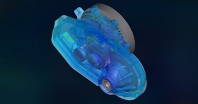
A recent application involved performing an NVH analysis on an electric vehicle drivetrain, which consists of an electric motor, a gearbox, and a power electronics module. The complex geometry of the drivetrain, with its numerous holes, gaps, and intersections, presented significant challenges for traditional meshing methods, taking up to 48 hours to create a mesh.
Using the acoustic meshing tool in Mechanical software, the team drastically reduced the mesh creation time from 48 hours to less than two hours (more than 90% reduction in time). The optimized mesh improved quality and performance, reducing solve time by 50%, computer memory (RAM) requirements by 70%, and file size by 75%. These advancements enabled faster and more accurate NVH analysis, improving overall product development efficiency.
What Is the Acoustic Meshing Feature?
The acoustic meshing tool in Mechanical software enables the creation of high-quality meshes for acoustic simulations with minimal user input. Based on wrapper meshing technology, the software quickly wraps a surface mesh around or inside the geometry without requiring geometry cleanup or connection. This eliminates the tedious steps of repairing and preparing the geometry for meshing, enabling engineers to focus on simulation setup and results.
The tool handles geometries with holes, gaps, and intersections, automatically closing them with the appropriate mesh size and element type. It can also generate different domain shapes and meshes depending on the simulation needs and solvers.
Improve Your Meshes in Four Steps
The acoustic meshing feature is guided by a simple workflow to optimize mesh quality and performance. The steps are as follows:
- Specify the frequency range and sound speed for the acoustic analysis. These parameters determine the mesh size and element type.
- Identify and name edges of holes that need closure. This manual step can be performed before or after launching the workflow. Holes below the mesh size are closed automatically.
- Launch the meshing workflow, guided by four stages: geometry preparation, surface meshing, domain creation, and volume meshing. Users can preview and adjust settings at each stage.
- Generate and review the mesh, including statistics and quality. The mesh can then be exported or imported for further analysis.
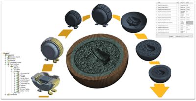
Mesh workflow steps, from the computer-aided design (CAD) file to acoustics radiation mesh
Benefits of the Acoustic Meshing Feature
The acoustic meshing tool offers numerous benefits, including:
- Reduced time and effort: Mesh generation for complex geometries takes minutes instead of hours or days.
- Enhanced accuracy and robustness: Meshes are optimized for acoustic analysis, with sizes and element types tailored to frequency and sound speed.
- Increased simulation flexibility and efficiency: Support for many domains, solvers, and boundary conditions reduces computational cost and enhances results.
See the Acoustic Meshing Workflow in Action
The acoustic meshing tool can be applied to acoustic simulations involving complex geometries, including external, internal, and boundary element method acoustics.
External Acoustics
External acoustics is one of the most common scenarios in acoustic meshing. The geometries involved are often complex, with multiple parts that may have gaps, overlaps, or even holes.
In the initial step, holes larger than the surface mesh size need to be identified and closed. To assist the meshing tool in detecting these holes, name selections are created for the boundary edges. There can be one or multiple such name selections, and this is the only manual step in the process. If no holes are present, this step can be skipped entirely. Using these name selections, the wrapper creates capping geometry surfaces, which users can review and either confirm or modify as needed.
Next, the wrapper generates a continuous surface mesh around the assembly. The surface mesh can be triangular or quadrilateral. Users have several options for volume meshing, ranging from regular spherical or rectangular shapes to more complex geometries like partial spheres or custom shapes.
Ansys now offers the body-fitted irregular perfectly matched layer (IPML) mesh, which adapts to the curvature of the assembly while minimizing mesh count. This is the default method. The IPML includes tetrahedral elements near the surface mesh, followed by layers of PML mesh, which can consist of hexahedral or prism-shaped elements. Pyramid elements are used to transition between the tetrahedral and hexahedral meshes. In specific cases in which the acoustic domain has a regular cuboid shapes, the acoustic mesh can consist entirely of hexahedral elements, avoiding the use of tetrahedral meshes altogether.
Users have complete control over the number of tetrahedral layers near the surface mesh, the number of PML layers, and the choice between quadratic or linear elements. To streamline customization, the entire process can be recorded and automated through scripting.
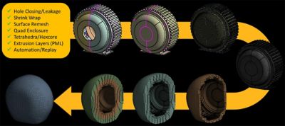
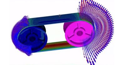
Original CAD file, wrapped surface mesh, and external radiation IPML mesh
Internal Acoustics
Simulating sound propagation in enclosed spaces, such as vehicle cabins, mufflers, or ducts, is crucial for understanding internal acoustics. However, creating a watertight acoustic region for complex geometries can be a significant challenge. The acoustic meshing wrapper simplifies this process by generating a continuous surface mesh in a single step. This surface mesh can consist of either triangular or quadrilateral elements. From this, a volume mesh is grown within the cavity. Near the surface, tetrahedral elements are created while the core region is populated with hexahedral elements. Pyramid elements are used to transition seamlessly between tetrahedral and hexahedral meshes. The mesh can be configured with either higher-order or linear elements. The hybrid meshing approach optimizes the mesh count, offering users control over the layers of tetrahedral elements. This enables defining growth rates to coarsen the hex-core mesh as needed. In specific cases in which the cavity has a regular cuboid shape, the acoustic mesh can consist entirely of hexahedral elements, avoiding the use of tetrahedral meshes altogether.

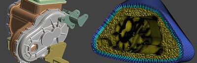
CAD to internal cavity mesh creation process
BEM Acoustics
Boundary element method (BEM) acoustics requires only a surface mesh on the geometry, as sound propagation inside the cavity or in a free field is solved using the Rayleigh integral method. This approach significantly simplifies the geometry preparation and meshing process. While hole closure is a necessary step for creating surface meshes in finite element method (FEM) acoustics, it is optional for BEM. The remaining steps to capture the surface of the assembly are similar to FEM meshing. The image below illustrates the surface mesh on the same motor housing assembly for BEM, where the holes are left as they are. With fewer steps needed to create a surface mesh, BEM meshing is the most straightforward approach to customize and automate using scripting.
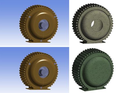
BEM acoustics surface mesh without and with hole closure
To learn more about the advanced acoustic meshing feature in Mechanical software, contact us for a demonstration.