-
United States -
United Kingdom -
India -
France -
Deutschland -
Italia -
日本 -
대한민국 -
中国 -
台灣
-
Ansys는 학생들에게 시뮬레이션 엔지니어링 소프트웨어를 무료로 제공함으로써 오늘날의 학생들의 성장을 지속적으로 지원하고 있습니다.
-
Ansys는 학생들에게 시뮬레이션 엔지니어링 소프트웨어를 무료로 제공함으로써 오늘날의 학생들의 성장을 지속적으로 지원하고 있습니다.
-
Ansys는 학생들에게 시뮬레이션 엔지니어링 소프트웨어를 무료로 제공함으로써 오늘날의 학생들의 성장을 지속적으로 지원하고 있습니다.

Space is a harsh environment. There’s no breathable air, radiation levels are 15 times higher than on Earth, and the approximate temperature is 2.7 Kelvin (minus 270.45 degrees Celsius or minus 454.81 degrees Fahrenheit). Thankfully, Earth’s atmosphere does a great job protecting us from space’s intense climate. But because there is no atmosphere in space, there’s nothing to protect satellites and other spacecraft from the extreme radiation and temperature fluctuations. The harshness of space can affect spacecraft components, including power electronics, guidance and navigation, and communications, all of which are critical functions. Because many spacecraft being launched are uncrewed, there’s almost no way to repair components should something go awry. To prevent mission failures, the reliability of the electrical components in the systems is paramount. Simulation solutions enable design teams to develop robust space platforms and maximize the probability of long-term success for these expensive programs by offering a means to accurately simulate a broad variety of instruments, materials, and orbital targets.
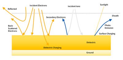
Conceptual diagram of physical processes involved in spacecraft charging
Galactic X-Rays
Much like people, systems on spacecraft are affected by short- and long-term radiation exposure.
- Short: Single-event effects (SEEs) are electronic disturbances caused by one highly energetic particle.
- Long: Total ionizing dose (TID) is the overall accumulated dose of radiation from different sources, including electrons, protons, heavy ions, x-rays, and gamma rays.
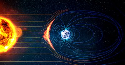
The sources of radiation most commonly are from particles trapped in Earth’s magnetic field, solar particle events (SPEs) during solar flares, and galactic cosmic rays (GCRs). The ionization of these particles can cause detrimental effects on spacecraft electrical systems. The particles cause a charge buildup that can’t dissipate because spacecraft are not grounded to anything. When charge accumulates, it induces electric fields. The magnitude of the electric fields may exceed the breakdown of air, plasmas, or dielectrics and lead to electrostatic discharges (ESDs). Studies show that about half of spacecraft anomalies are caused by spacecraft charging effects.
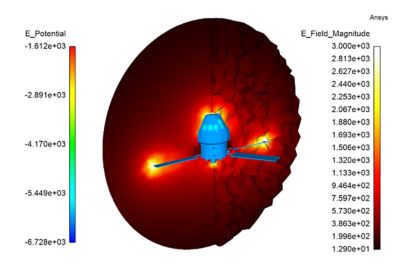
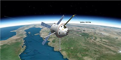
The results of the surface charging simulation of a human space capsule. The electric field is monitored in the time domain, in 3D, around the spacecraft.
Surface Charging Risk Assessment
Surface charging comes from a material response to external radiation, such as ambient charged particles, photo-illumination, and triboelectrification. The material response to the charging effects depends on the material’s properties. The resulting photoelectrons, secondary electrons, back-scattered electrons, and proton-induced electrons interact with the electric fields to form a plasma sheath.
On the way to the Moon, for example, spacecraft encounter surface charging effects of varying scales depending on the transfer orbits. Geostationary orbit (GEO), low-Earth orbit (LEO), and polar, auroral, and lunar orbits all have different plasma environments defined in the design specification standards. Geometry, shadows, and the material properties, in addition to the plasma properties or the triboelectrification amplitude, play a role in the charge accumulated at the surface of the spacecraft.
Ansys Charge Plus electromagnetic charging and discharge simulation software uses numerous material properties to track the balance of charge between the surface and environment of the spacecraft. The particle-in-cell (PIC) solver, coupled with the boundary element method (BEM), makes it possible to analyze the spacecraft’s charge, examine the distribution of the surrounding plasma state, and plot the electron distribution. Surface charging using full-wave finite element method (FEM) electromagnetic field analysis enables engineers to calculate the fields in 3D around the spacecraft and get more information about whether there is a risk of arcing in the plasma.
Internal Charging of Bulk Material
Internal dielectric charging occurs from the interaction of charged particles from the Sun (and high-energy photons) and the bulk material of the spacecraft. These particles may be accelerated by solar flares or by Earth’s magnetic field, such as in the Van Allen belts or near the poles. The charge deposited by these particles induces fields that can lead to dielectric breakdown. By modeling the charge deposition rate and magnitude, engineers can refine their radiation hardening designs, estimate the risk of ESD, and simulate currents induced on electronics.
In plasma environments, where the energy of charged particles is high enough to result in deep dielectric charging, engineers are often concerned with the risk of charge accumulation inside sensitive components, such as solar cells, sensors, and exposed cables or connectors. To assess the risk of ESD in a dielectric, engineers can use high-energy spectrum information exported from the Ansys Systems Tool Kit Space Environment and Effects Tool (STK-SEET) capability and then use Charge Plus software to couple a 3D particle transport tool with a full-wave FEM solution of electromagnetism solved in the time domain. With this method, engineers can monitor potential, fields, charge, and currents induced by the interaction of particles with bulk materials. The particles can be incident upon a variety of geometric configurations, their energy spectrum can be time dependent, and multiple types of particles can be simulated at once.
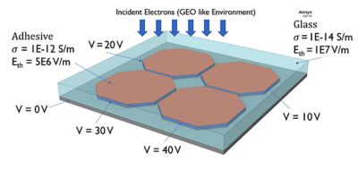
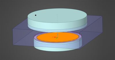
A model setup for the breakdown of a solar cell coupon with the bias voltage applied to each cell and with the properties of the materials. Electrons from a geosynchronous environment were shined from the top with a planar geometry.
Solid Dielectric Breakdown of Solar Cells
If there is too much charge in the system, then the resulting electric fields will exceed the breakdown threshold of the medium. Discharges occur from the spacecraft to the plasma, from one conductor to another across plasma or air, or directly inside a dielectric/insulator. At worst, these discharges can lead to secondary arcing if the spacecraft isn’t well grounded. Additionally, ESDs radiate electromagnetic radiation, which can damage communication systems.
For example, too much charge accumulated in a cable connected to sensitive electronics may induce currents that damage the instruments. In some cases, due to design constraints, engineers have to accept a minimal amount of primary arcing in the spacecraft. In other instances, a design tailored for a specific radiation environment, such as LEO, may need to be reused in a harsher radiation environment, such as GEO.
To simulate dielectric breakdown, Charge Plus software leverages a full-wave electromagnetic solver and a stochastic tree model that calculates the probability of breakdown as a function of electric field, dielectric strength of the material, and coupling strength to adjacent nodes. That probability distribution is evaluated at each time step and at each node of the FEM mesh used for the problem.
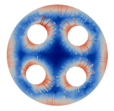
The electric field in the dielectric surrounding the pins reached levels that are near the dielectric strength of a typical insulator.
That’s Rad Hard
While simulation enables engineers to see how their spacecraft’s electronic components will behave in space, it doesn’t make the systems immune to radiation effects. But it can enable engineers to design and test radiation-hardened — commonly called rad hard — electrical components. Charge Plus software uses Monte Carlo 3D particle transport and FEM to track particle fluences during simulations and use fields as feedback to the transport problem. Engineers can then evaluate the amount of radiation penetration into the interior of different metal thicknesses. This enables engineers to design the metal thickness to balance the weight of the craft with the impact of radiation hardening.
Learn More
The Advantage Blog
The Ansys Advantage blog, featuring contributions from Ansys and other technology experts, keeps you updated on how Ansys simulation is powering innovation that drives human advancement.


