-
United States -
United Kingdom -
India -
France -
Deutschland -
Italia -
日本 -
대한민국 -
中国 -
台灣
-
Ansys는 학생들에게 시뮬레이션 엔지니어링 소프트웨어를 무료로 제공함으로써 오늘날의 학생들의 성장을 지속적으로 지원하고 있습니다.
-
Ansys는 학생들에게 시뮬레이션 엔지니어링 소프트웨어를 무료로 제공함으로써 오늘날의 학생들의 성장을 지속적으로 지원하고 있습니다.
-
Ansys는 학생들에게 시뮬레이션 엔지니어링 소프트웨어를 무료로 제공함으로써 오늘날의 학생들의 성장을 지속적으로 지원하고 있습니다.
ANSYS BLOG
January 6, 2021
How the SAE J3168 Standard Will Improve Automotive Electronic Hardware
The race is on for fully autonomous vehicles. Industry giants like Tesla, Google, Uber and almost all major automotive companies are competing to deliver state-of-the-art self-driving vehicles.
However, the development of new, cutting-edge technologies demands a similar wave of reliability, repairability and warranty standards that automotive manufacturers must implement as technological capabilities reach new heights.
A New Era of Electronic Reliability Standards
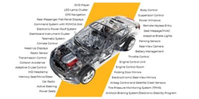
Automotive electronics typically account for at least 35% of a modern automobile.
“Electronics will account for 35% of the cost of a car soon … and with autonomous driving coming by 2030, PWC thinks it will soon account for 50% of the car,” writes Michael Schuldenfrei in a recent Semiconductor Engineering article. Schuldenfrei is corporate technology fellow at Optimal Plus. “If you think about where cars are today and where they’re going to be tomorrow, this is a problem.”
Consumers are much less likely to purchase a vehicle from a manufacturer if the vehicle’s electronics experience repeated failures, and some original equipment manufacturers (OEMs) are even calling for automotive electronics that last up to 20 years. To meet this demand, automotive manufacturers will need to implement new standards and workflows that produce electronic hardware that is reliable and repairable, and that have much longer warranties.
Learn more about automotive electronics reliability challenges.
What is the SAE J3168 Standard?
SAE J3168 is the first reliability physics analysis (RPA) standard developed specifically for use in the aerospace, automotive, defense and other high-performance (AADHP) industries.
In 2020, the SAE Automotive Electronic Systems Reliability Standards Committee and the SAE Avionics Process Management Committee passed the SAE J3168 standard: “Reliability Physics Analysis of Electrical, Electronic, Electromechanical Equipment, Modules and Components.” It is the first reliability physics analysis (RPA) standard developed specifically for use in the aerospace, automotive, defense and other high-performance (AADHP) industries.
The use of RPA has proliferated in the last two decades, but there is wide variation in the ways it has been conducted. The potential for inconsistency and misinterpretation has increased as technology has progressed, leading to the development of SAE J3168 to formalize a consensus among users and document standard methods to apply RPA to electrical, electronic and electromechanical (EEE) equipment, modules and components.
RPA is the process of using scientifically derived algorithms and robust simulation techniques to predict how the evolution of physical, chemical, mechanical, thermal or electrical mechanisms cause degradation and eventually induce failure. All engineers involved in design and validation can leverage RPA to identify and mitigate potential risks before hardware prototyping, saving their organizations resources, time and unforeseen costs.
Improving Automotive Electronics Reliability with SAE J3168
SAE J3168 describes a baseline process to assess board-level reliability and durability with respect to five major potential failure mechanisms:
- Solder joint fatigue due to thermal cycling
- Solder attachment fatigue due to vibration
- Solder joint failure due to mechanical shock
- Printed circuit board (PCB) via hole fatigue due to thermal cycling
- Aging and wear out of microcircuits due to electromigration, oxide breakdown, bias temperature instability and hot carrier injection.
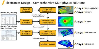
For example, the first step in evaluating the risk of solder fatigue due to thermal cycling requires a strong understanding of the potential environment. Minimum and maximum temperatures, ramp rates and dwell times must all be accounted for. Localized temperature increases due to power dissipation must also be captured. This requires a seamless integration between your RPA tool and thermal analysis results. This is the exact workflow implemented by Ansys, where Ansys Sherlock (RPA) and Ansys Icepak (thermal analysis) have a unique two-way exchange of information. This provides confidence to the end customer that all important parameters of solder fatigue have been incorporated into the RPA activity.
An integrated electronics reliability workflow with Ansys HFSS, Icepak, Mechanical, Sherlock and SIwave
Request an electronics reliability demo.
Incorporating detailed design information is also critical. Assumptions about part and PCB geometry can lead to significant deviations between prediction and actual performance during validation testing. Sherlock supports this requirement in two ways.
The first is through its comprehensive part and package libraries that contain detailed information on external dimensions as well as die, overmold, lead and solder ball geometry. This library is not static and can be tailored and enhanced per specific customer requests.
The second way Sherlock supports detailed design information is via its ability to parse electronic computer-aided engineering (ECAD) files and provide the user with a wide variety of geometries and element types ready for finite element analysis (FEA). These include layers with effective properties, trace meshing, trace modeling and reinforcements. This one-of-a-kind capability among CAE tools provides Sherlock users with key insight into PCB features, such as bond pad sizing and via stacks, that play an increasingly important role in solder joint failure.
Testing and analysis are critical components for developing reliable electronic products. It is essential that design engineers and electronic manufacturers have access to simulation tools that can simulate use environments and potential failure mechanisms, and determine if the product meets the standards laid out in SAE J3168. As technology progresses, simulation tools will become the primary solution for solving reliability and failure risks early in the product design stage without having to rely on physical testing.


