-
United States -
United Kingdom -
India -
France -
Deutschland -
Italia -
日本 -
대한민국 -
中国 -
台灣
-
Ansys는 학생들에게 시뮬레이션 엔지니어링 소프트웨어를 무료로 제공함으로써 오늘날의 학생들의 성장을 지속적으로 지원하고 있습니다.
-
Ansys는 학생들에게 시뮬레이션 엔지니어링 소프트웨어를 무료로 제공함으로써 오늘날의 학생들의 성장을 지속적으로 지원하고 있습니다.
-
Ansys는 학생들에게 시뮬레이션 엔지니어링 소프트웨어를 무료로 제공함으로써 오늘날의 학생들의 성장을 지속적으로 지원하고 있습니다.
ANSYS BLOG
December 1, 2022
Three’s Company: Simulation, Optimization, and Measurement-Based Modeling Ease RF and Microwave Filter Design
A critical part of antenna design involves the supporting circuitry — and central to the system design is the development and implementation of filters. Essentially, filters are the gatekeepers of frequency. Simply put, filters allow desired frequencies and signals into your projects and block unwanted frequencies and signals.
Common types of radio frequency (RF) filters include:
- Low pass: allowing frequencies lower than the cutoff frequency to pass through
- High pass: allowing frequencies higher than the cutoff frequency to pass through
- Band pass: allowing frequencies within a certain range to pass through
- Band stop: blocking frequencies within a certain range from passing through
Filters can be implemented in an RF board or module design in several forms, such as discrete or ‘lumped’ elements (surface-mount components), low temperature co-fired ceramic (LTCC), microstrip, stripline, and incorporated into integrated circuits (ICs or chips).
Building filters becomes even more challenging at higher frequencies because it takes great precision to determine the specific combination of values and components needed to effectively design a filter to function.
Modelithics alleviates this burden with the help of Ansys HFSS 3D high-frequency electromagnetic (EM) simulation and Ansys Nuhertz FilterSolutions design software. Modelithics offers comprehensive measurement and modeling tools for RF, microwave, and millimeter-wave components, including the Modelithics COMPLETE Library and measurement-based component models that integrate seamlessly with HFSS and Nuhertz.
Through optimization and critical insight, the three tools significantly accelerate the design of lumped element filters with discrete resistor, inductor, and capacitor (RLC) components in high frequencies.

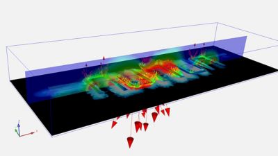
Ansys HFSS simulation models a hairpin resonator microstrip filter (a type of bandpass filter). The graphic overlays depict the ground plane currents. The cross-plane shows magnetic (H) field magnitude along that slice, while the arrays and flow lines (the arrows and lines at the bottom) show the electric field vectors.
Optimizing Filter Design
RF filters have very specific printed circuit board (PCB) manufacturing requirements and require careful materials selection. Compounding the challenge, surface mount components can also be fickle. For starters, they can behave differently depending on the circuit board they are placed on because each component creates a small local EM field that can couple with the circuit board and react unpredictably. Furthermore, discrete component values will have a range within a certain tolerance, leading to inexact “standard” values.
Modelithics helps greatly in this area by providing measurement-based component models for the discrete component values to include their coupling to different kinds of substrates with various sizes of landing pads. When you solder components onto a circuit board, the size of the pad — typically a very short metal trace that is wider than its connecting line — makes a difference, especially at higher frequencies.

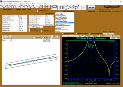
Ansys Nuhertz FilterSolutions provides automated radio frequency (RF), microwave, and digital filter design, synthesis, and optimization. It starts with your filter performance specifications, synthesizes both lumped component and physical filter layout realizations, and automatically sets up filter analysis and optimization in the Ansys HFSS electromagnetic (EM) simulator.
Modelithics simplifies the process by providing a comprehensive model library for surface-mount parts, which includes information regarding the impact of the part on your design. Further, the Modelithics part library includes the surface, substrate, or circuit board to which you are soldering the component as a parameter. The models also provide parameters to relate the size of the mounting pad.
With the ability to select accurately sized components and materials, you gain better insight into your design and decrease design risk and the potential for failure.
You can access the Modelithics library from Nuhertz or HFSS. Nuhertz provides automated filter design, synthesis, and optimization in a straightforward and seamless manner. Using your filter performance specifications, Nuhertz synthesizes your lumped components and automatically sets up filter analysis and optimization in HFSS.
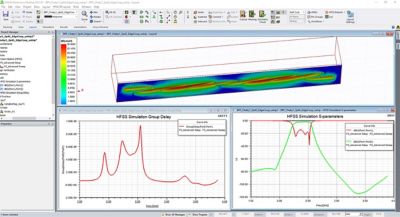
HFSS excels at EM simulation and enables you to design and simulate high-frequency electronic products such as RF and microwave components, filters, connectors, PCBs, antennas, and more. First, the standard-value components are optimized. In a second process, the planar interconnects are then optimized, along with the standard-value components to ensure that the EM impacts of both discrete components and their interconnects yield the best design to fit performance specifications. If desired, shield, enclosure effects, and substrate edge connectors can be included in the overall optimization.

Ansys HFSS 3D electromagnetic (EM) simulation enables designers to model high-frequency electronic products such as antennas, antenna arrays, radio frequency (RF) or microwave components, high-speed interconnects, filters, connectors, integrated chip (IC) packages and printed circuit boards.
There are two modes in HFSS: 3D mode and 3D layout mode, which is best for designers who work with layered board geometries or layout high-speed components such as IC packages, on-chip embedded passives, and PCB interconnects.
HFSS can also use ready-made 3D Component models for simulation, including RF connectors and surface-mount devices (e.g., chip capacitors and inductors). A 3D Component model contains all relevant information — including materials, geometry, design parameters, and boundary conditions — and can be integrated into a 3D EM simulation. Many component vendors offer HFSS 3D Components to customers so that they can incorporate them directly into their designs.

The 3D Component feature in Ansys HFSS enables designers to model discretely and out of view thanks to patented encryption technology.
This separate 3D Component feature can be used in either mode (3D or 3D layout) and acts as a “black box” for your model, keeping the details of its interior design and materials hidden from view.
A patented encryption technology allows component providers to hide and protect critical intellectual property (IP), while fully describing their parts for downstream simulation.
For example, a manufacturer can model a surface-mount part such as a discrete inductor or capacitor and deliver it in a way that no one can see inside of it. This is beneficial if another manufacturer is developing a filter and wants to use that model and simulate it in the context of a larger board design.
In addition to privacy, it also provides an accurate EM interaction with the base design — including other 3D Components — through its outer boundaries, and its ports can make electrical connection to conductors (like mounting pads) in the base design.
Combating Challenges
As with many products and industries, one of the top challenges in RF/microwave filter design is ensuring the design will work successfully when you build it. Physical testing is costly and time-consuming. With simulation, you can virtually design, test, and ensure the success of your product before creating the physical prototype. This is especially beneficial when you are producing filters in mass quantity and process yields are important.
Most engineers and designers in this position are plagued by two questions: can I build a million of these filters reliably, and how many will pass the specifications?
This is one of the primary challenges that the Nuhertz-Modelithics-HFSS workflow helps to overcome by equipping engineers and designers with confidence in their designs through insight and optimization.
The top benefits of the workflow include design optimization, automation, increased manufacturing yields, insight into process corners and yields, reduced time to market, and reduced material costs.
Another hurdle for RF/microwave filter designers is getting the right parts. Discrete inductors, capacitors, and resistors are only offered at certain standard values. Nuhertz alleviates this challenge by helping you select components while taking standard values into account. This is a significant part of the optimization capability of Nuhertz- helping you find the standard value components that come closest to satisfying the performance requirement of the circuit or filter you are working with. Equally advantageous, the software also delivers insight into how the interconnect between the components will impact your design.
Discover the Tools
Nuhertz enables you to quickly and efficiently synthesize filters that meet your performance requirements and then open your filter designs in HFSS for immediate EM analyses and optimization. The Modelithics Microwave Global Model library, accessible in Nuhertz and HFSS, provides a comprehensive library to equip you with accurately measured components throughout the entire modeling process to ensure your design meets specification requirements.
To learn more about the Nuhertz-Modelithics-HFSS workflow request a free trial of Nuhertz.


