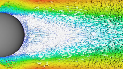
Il flusso laminare si verifica quando le particelle in un fluido si muovono in una direzione con un movimento limitato o completamente assente perpendicolare alla direzione del flusso. Il flusso turbolento si verifica quando le particelle di fluido si muovono perpendicolarmente alla direzione del flusso, di solito in spirali chiamate vortici. Le caratteristiche del fluido, come portata, densità e viscosità, insieme alla geometria degli oggetti nei quali o attorno ai quali il fluido scorre, determinano quando si verifica la transizione del flusso da laminare e quanto è caotico il regime del flusso turbolento.
Questa caratteristica fondamentale del flusso di un fluido influisce su tutto, dal rumore prodotto da un'auto all'efficienza nel consumo di un carburante di un aeromobile fino alla velocità con cui le sostanze chimiche si mescolano. Sebbene sia teoricamente possibile un flusso laminare completo, è piuttosto raro nel mondo reale, pertanto gli ingegneri devono prevedere e gestire il flusso laminare e turbolento all'interno e attorno agli oggetti che stanno progettando.
Termini chiave utilizzati nella caratterizzazione del flusso
Un ottimo punto di partenza per capire la differenza tra flusso laminare e flusso turbolento è definire alcuni dei termini critici utilizzati dagli ingegneri per descrivere la caratterizzazione del flusso.
Strato limite
Uno strato limite è un sottile strato di fluido vicino a una superficie oltre la quale passa il fluido, in cui la velocità varia da zero sulla superficie alla velocità di flusso libero del fluido. La viscosità del fluido crea una condizione limite anti-scivolamento sulla superficie. Velocità di flusso libero, lunghezza di corsa, viscosità e quantità di turbolenza nello strato limite determinano lo spessore del limite.
Velocità di massa
Il termine velocità di massa si riferisce alla velocità media complessiva di un fluido. Viene calcolata misurando la velocità di flusso del volume divisa per l'area trasversale del piano di misurazione.
Vortice
Un vortice è il movimento delle particelle di fluido che devia dalla direzione generale del flusso del fluido. I vortici possono essere un mulinello, un turbinio o semplici fluttuazioni attorno alla direzione del flusso dominante.

Separazione del flusso o separazione dello strato limite
La separazione del flusso si verifica quando il flusso dello strato limite si allontana da una superficie quando la velocità vicino alla superficie viene invertita a causa di un gradiente di pressione avverso.
Flusso libero
Il flusso libero è l'area di flusso al di fuori degli strati limite.
Flusso interno ed esterno
Il flusso interno descrive le situazioni in cui il fluido è delimitato da un solido su tutti i lati perpendicolari alla direzione del flusso. Il flusso esterno descrive il fluido attorno a un oggetto. I fluidi si comportano in modo diverso se scorrono all'interno di qualcosa, come il flusso di un tubo, o attorno a qualcosa, come un'ala di un aereo.
Equazioni di Navier-Stokes
Le equazioni di Navier-Stokes sono una serie di equazioni che descrivono il flusso di fluidi viscosi. I programmi di fluidodinamica computazionale (CFD, Computational Fluid Dynamics) combinano le equazioni di Navier-Stokes con equazioni aggiuntive per prevedere il comportamento della maggior parte delle situazioni di flusso di un fluido.
Regime di flusso
Il regime di flusso, o modello di flusso, è una descrizione della struttura e del comportamento di un flusso. Il regime di flusso è determinato da caratteristiche quali velocità, viscosità, fase e flusso laminare o turbolento.
Numero di Reynolds (Re)
Il numero di Reynolds è un valore senza dimensioni che caratterizza il rapporto tra le forze inerziali e viscose nel flusso di un fluido. Il valore deriva dagli esperimenti di Osborne Reynolds per capire come l'acqua fluisce in un tubo e quando avviene la transizione da laminare a turbolento. Il rapporto tra forze interne e viscose prevede quando il flusso passerà da laminare a turbolento.
L'equazione del numero di Reynolds è:
ρ = densità del fluido (kg/m3)
u = velocità del flusso (m/s)
L = dimensione caratteristica, ad esempio diametro del tubo, diametro idraulico, diametro equivalente, lunghezza corda di un profilo alare (m)
μ = viscosità dinamica del fluido (Pa·s)
v = viscosità cinematica (m2/s)
Profilo di velocità
Un profilo di velocità è la velocità del flusso del fluido lungo una linea retta arbitraria o una superficie piana. La linea o la superficie piana è generalmente orientata perpendicolarmente alla direzione del flusso di massa o a una superficie. I profili di velocità mostrano il gradiente di velocità in uno strato limite e vengono utilizzati per calcolare le velocità del flusso di massa.
Viscosità
La viscosità di un fluido è una misura della resistenza alla deformazione a una determinata velocità. Caratterizza le forze di attrito interne tra strati paralleli di fluido.

Cos'è il flusso laminare?
Il flusso laminare è una condizione di flusso in cui le particelle del fluido seguono linee di flusso uniformi e costanti con un movimento minimo delle particelle tra strati adiacenti. Il flusso laminare è caratterizzato da numeri di Reynolds relativamente bassi perché le forze viscose sono molto più grandi della velocità. Il tipo di fluido e le proprietà del fluido, insieme alla geometria e alla ruvidità della superficie di eventuali oggetti solidi attorno o attraverso i quali il fluido scorre, contribuiscono a quanto tempo il flusso rimarrà laminare. Il profilo di velocità di un flusso laminare aumenta monotonicamente da zero alla velocità del flusso libero attraverso lo strato limite.
Cos'è il flusso turbolento?

Il flusso turbolento è caratterizzato da variazioni caotiche nella grandezza e nella direzione della velocità delle particelle del fluido e nell'ampiezza della pressione. Il flusso turbolento è caratterizzato da numeri di Reynolds elevati, in cui la velocità e la dimensione caratteristica sono molto più elevate dello smorzamento viscoso del fluido. Il livello alto dipende dalle proprietà del fluido e dall'oggetto nel quale o attorno al quale il fluido scorre. Il flusso turbolento è altamente irregolare e quasi impossibile da prevedere o misurare nei dettagli. Per questo motivo, gli ingegneri trattano la turbolenza da un punto di vista statistico.
Perché è importante comprendere sia il flusso laminare che quello turbolento?
Gli ingegneri si preoccupano del flusso laminare e turbolento perché ogni regime di flusso influisce sulla fisica del fluido con cui stanno lavorando. A volte si potrebbe voler mantenere il flusso laminare il più a lungo possibile e in altri casi potrebbe essere necessaria turbolenza. Ecco alcune situazioni di cui gli ingegneri devono essere a conoscenza e il ruolo dei diversi modelli di flusso.
Trasferimento di calore
Il movimento del calore da un oggetto a un fluido dipende principalmente dalla velocità del flusso sia in direzione opposta che perpendicolare alla superficie. Velocità e turbolenza elevate aumentano il flusso di calore da un oggetto al fluido che lo circonda. Spesso gli ingegneri progettano di aumentare la turbolenza nelle situazioni di riscaldamento e raffreddamento per massimizzare il trasferimento di calore tra un oggetto e un fluido.
Sollevamento
Il sollevamento è una forza netta su un lato di un oggetto solido con fluido che scorre attorno all'oggetto causato da un aumento di pressione su un lato e un calo di pressione sull'altro. La turbolenza all'interno dello strato limite può aumentare il differenziale di pressione, ma livelli elevati di turbolenza nel flusso libero possono ridurre il sollevamento o causare forze oscillanti indesiderate sull'oggetto che genera sollevamento.
Trascinamento
Il trascinamento è una forza esercitata dal fluido all'interno oppure oltre un oggetto, applicata nella direzione del flusso. Nella maggior parte dei casi, la turbolenza in uno strato limite aumenta il trascinamento su un oggetto. I progettisti dedicano molto tempo a simulazione e gallerie del vento, mettendo a punto l'aerodinamica di veicoli e aeromobili per ridurre al minimo il trascinamento.
Rumore
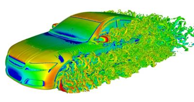
Quando il flusso di aria intorno a un oggetto passa a turbolento, i vortici possono creare onde sonore nella gamma di frequenze udibili. Il rumore non solo rappresenta uno spreco di energia, ma può anche essere sufficientemente intenso da risultare fastidioso o addirittura dannoso per la salute.
Miscelazione
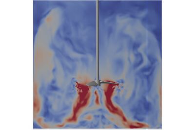
Un'area in cui la turbolenza può essere una buona cosa è la miscelazione. Nella combustione, nel trattamento delle acque e nella produzione chimica, gli ingegneri progettano sistemi in cui il flusso caotico di turbolenza mescola fluidi diversi per migliorare la velocità e l'efficienza delle reazioni chimiche.

Modellazione del flusso laminare e turbolento nella simulazione
Il flusso laminare è ben caratterizzato dalla risoluzione delle equazioni Navier-Stokes in uno strumento CFD di uso generale come il software di simulazione dei fluidi Ansys Fluent o uno strumento dedicato a macchinari rotanti come il software Ansys CFX. Le stesse equazioni possono prevedere il flusso turbolento, ma i requisiti computazionali per la simulazione numerica diretta del flusso turbolento non sono pratici. Il numero di equazioni necessarie per modellare un vortice è dell'ordine del numero di Reynolds cubico. Per questo motivo, gli utenti aggiungono ulteriori equazioni a un modello che si avvicina al comportamento turbolento con una precisione sufficiente a rispondere a domande tecniche.
Ansys offre diverse risorse, tra cui corsi online gratuiti su come modellare correttamente il flusso laminare e il flusso turbolento. Ecco alcune linee guida di base per creare solide fondamenta:
Modellazione del flusso laminare in CFD
La modellazione del flusso laminare è semplice in uno strumento CFD. L'attività più importante nella modellazione del flusso laminare è avere una precisione sufficiente per prevedere quando il flusso diventerà un flusso turbolento. La mesh deve includere una risoluzione sufficiente negli strati limite per acquisire accuratamente il profilo di velocità. È inoltre importante specificare una ruvidità precisa delle pareti e acquisire la geometria della superficie con una risoluzione sufficiente.
Previsione della transizione da flusso laminare a flusso turbolento in CFD
Anche se osservando la gamma di numeri di Reynolds in un modello è possibile decidere dove si verifica il flusso transizionale, gli intervalli consigliati si riferiscono a casi ideali che raramente si verificano nelle applicazioni reali. Se si ipotizza un flusso turbolento lungo l'intera lunghezza di un modello, è possibile prevedere lo sforzo di taglio alla parete. Ansys ha aperto la strada alla previsione numerica del flusso di transizione fondata sul concetto di modellazione di transizione basata sulla correlazione locale (LCTM, Local Correlation based Transition Modeling). Per ottenere questo risultato, utilizzare un modello di turbolenza che includa equazioni che predicono con precisione il flusso transazionale.
Modelli di Navier-Stokes mediati da Reynolds (RANS, Reynolds-Averaged Navier Stockes) per la turbolenza
Esistono due classi di equazioni semplificate per il flusso turbolento. La prima classe è rappresentata dai modelli RANS. Questo approccio decompone le quantità di flusso nei relativi componenti fluttuanti e in media temporale. I modelli RANS sono approssimazioni basate su studi empirici. Sono disponibili numerosi modelli RANS. Di seguito sono riportati alcuni dei modelli RANS più comunemente utilizzati:
- Spalart-Almaras (SA): Un semplice modello a singola equazione utilizzato nell'aerodinamica esterna.
- Modelli a due equazioni: Una famiglia di modelli RANS basati sulle formulazioni k-ε e k-⍵ meno recenti I modelli SST (Shear stress Transport), BSL (Baseline) e k-⍵ generalizzati (GEKO) vengono utilizzati in modo indipendente o in combinazione per prevedere con precisione il flusso turbolento nelle applicazioni industriali.
Alcune best practice per l'utilizzo dei modelli RANS sono:
- Rappresentare la geometria nel modo più accurato possibile
- Mantenere gli ingressi e le uscite in aree di flusso ben definito
- Assicurarsi che le proprietà del fluido, come densità e viscosità, siano accurate
- Posizionare risoluzione ottima in strati limite e passare gradualmente alle regioni di mesh più grossolana
- Utilizzare affinamento della mesh iterativa per convergere su una griglia precisa
- Utilizzare condizioni di limite accurate
- Se possibile, utilizzare valori numerici di secondo ordine
- Ripetere l'iterazione su diversi modelli RANS o parametri all'interno di un modello per corrispondere ai dati sperimentali
Modelli di simulazione con risoluzione in scala (SRS, Scale-Resolving Simulation) per la turbolenza
La seconda classe di modelli di turbolenza, la simulazione con risoluzione in scala, risolve il problema del flusso di un fluido turbolento nel tempo e nello spazio piuttosto che in media nel tempo. La maggior parte delle applicazioni del sistema SRS utilizza modelli LES (Large Eddy Simulation) per risolvere i vortici più grandi durante la modellazione dei vortici più piccoli. I modelli LES sono stati migliorati e convalidati nel corso del tempo. Rispetto ai modelli RANS, richiedono più cellule e tempi di esecuzione più lunghi.
Aumenti di capacità di elaborazione, in particolare l'uso di GPU, consentono l'uso di modelli SRS per flussi industriali con una varietà di modelli ibridi SRS/RANS, tra cui:
- SAS (Scale-Adaptive Simulation)
- DES (Detached Eddy Simulation)
- SDES (Shielded Detached Eddy Simulation)
- SBES (Stress-Blended Eddy Simulation)
- ELES (Embedded LES)
Le best practice per utilizzare correttamente i modelli SRS, in particolare i modelli LES, sono molto diverse da quelle per i modelli RANS. È particolarmente importante mantenere celle con rapporto di aspetto basso, poiché i vortici di turbolenza devono essere risolti in tutte e tre le direzioni di spazio. Inoltre, si applicano restrizioni temporali rigorose per garantire una corretta risoluzione temporale del campo di turbolenza. Infine, la qualità LES dipende fortemente dalla disponibilità di trattamenti numerici specializzati per ridurre al minimo l'impatto della dissipazione numerica.
Scopri di più sull'ampia gamma di modelli di turbolenza del software Fluent, incluso il modello k-ω generalizzato (GEKO) generalizzato leader del settore.
Solo per te. Abbiamo alcune risorse aggiuntive che potrebbero essere utili.
Ulteriori informazioni
Ansys ha creato una serie di documenti sulle best practice per aiutare a comprendere meglio le ipotesi del modello sottostante e il modo migliore per applicare questi modelli.
Best Practice: Modellazione della turbolenza RANS in Ansys CFD
Best Practice: Modellazione della turbolenza a due equazioni k- (GEKO) generalizzato in Ansys CFD
Best Practice: Simulazioni in risoluzione in scala in Ansys CFD


