


THEMENDETAILS
Was ist Knotenanalyse?
Die Knotenanalyse ist eine Methode zur Berechnung der Spannung an den Verbindungen, die Knoten genannt werden, zwischen Komponenten in einem elektrischen Stromkreis. Sie ist ein grundlegender Bestandteil der Schaltungsanalyse für alles, von einer einfachen drahtgebundenen Schaltung, die diskrete Komponenten verbindet, bis hin zu komplexen integrierten Schaltungen (ICs).
In einer einfachen Knotenanalyse wird jede Verbindung zwischen Komponenten – den Leiterbahnen oder Drähten – als Knoten bezeichnet. Kirchoffsche Gesetze und Ohmsche Gesetze werden verwendet, um Gleichungen zu schreiben, die den Widerstand, Strom und Spannung jedes leitenden Pfades betreffen, der zu jedem Knoten führt. Das Gleichungssystem wird dann von Hand oder unter Verwendung einer linearen Algebra für den Spannungsabfall an jedem Knoten gelöst. Bei größeren Problemen wird Software, in der Regel in Form eines SPICE Schaltungssimulators, zur Durchführung von Knotenanalysen verwendet.
Die Grundgesetze der Knotenanalyse
Die Methode der Knotenanalyse basiert auf drei Grundgesetzen:
1. Kirchhoffscher Knotensatz (KCL)
Die algebraische Summe aller Ströme, die einen Knoten betreten und verlassen, muss gleich Null sein.
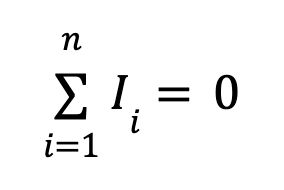
I steht für Strom und n für die Anzahl der Verzweigungen, die in den Knoten hineinfließen.
2. Kirchhoffscher Maschensatz (KVL)
Die algebraische Summe aller Potentialdifferenzen (Spannungen) in einer Masche muss gleich Null sein.
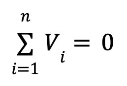
V steht für Spannung und n für die Anzahl der Punkte, an denen Spannung um die Masche gemessen wird.
3. Ohmsches Gesetz
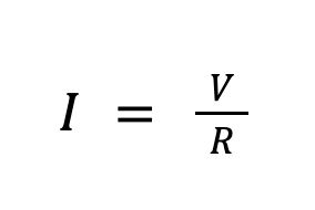
Der elektrische Strom (I) durch einen Leiter ist gleich der Spannung (V) über den Leiter geteilt durch den Widerstand (R) des Leiters.
Terminologie der Knotenanalyse
Für eine Knotenanalyse wird ein Schaltplan verwendet, um ein Netzwerk der folgenden Elemente darzustellen:
Referenzknoten: Ein Knoten im Stromkreis, in dem die Spannung bekannt ist. Dies ist in der Regel ein Masseknoten, und die Spannung ist auf 0 eingestellt.
Knoten ohne Referenz: Jeder Knoten, in dem die Spannung unbekannt ist
Spannungsquelle: Eine Komponente im Stromkreis, bei der das Potential durch eine bekannte Spannung geändert wird
Stromquelle: Eine Komponente mit einem bekannten Strom
Superknoten: Wenn eine Spannungsquelle zwei unbekannte Spannungen auf beiden Seiten hat, kann sie in einen Superknoten umgewandelt werden, in dem die Ströme der beiden Knoten zu einer einzigen Gleichung zusammengefasst werden. Eine neue Gleichung für die Spannungs-Strom-Beziehung des Superknotens kann dann geschrieben werden.
Bauteil: Ein elektronisches Gerät mit einer bekannten Beziehung zwischen Spannung und Strom. Bei einem Widerstand basiert diese Beziehung auf dem Widerstand. Sie wird oft als Admittanz oder als Kehrwert des Widerstands ausgedrückt. Bei einem Kondensator hängt die Beziehung vom Verhältnis zwischen Kapazität und Spannungsänderung im Zeitverlauf ab.
Modifizierte Knotenanalyse: Bei komplexeren Schaltungen reicht eine einfache Knotenanalyse möglicherweise nicht aus, um alle unbekannten Spannungen zu finden. In Fällen, in denen die Strom-Spannung-Beziehung eines Bauteils komplizierter als das Ohmsche Gesetz ist, wird eine modifizierte Knotenanalyse durchgeführt.
Netzanalyse: Wenn Ströme nicht bekannt sind, wird das Kirchhoffsche Spannungsgesetz in einer Netzanalyse verwendet, um die unbekannten Zweigströme zu finden.
Warum ist die Knotenanalyse wichtig
Elektronische Schaltungen sind für die Übertragung von elektrischem Strom ausgelegt, um Strom und ein Signal zu liefern. Ingenieur*innen, die Schaltungen entwickeln, müssen wissen, dass die von ihnen definierte Elektronik wie erwartet funktioniert. Die Knotenanalyse wird durchgeführt, um die Knotenspannungen und Stromflüsse für jeden Teil der Schaltung zu berechnen. Sobald diese Grundwerte bekannt sind, kann eine komplexere Analyse durchgeführt werden, um die Signalintegrität, die Erwärmung und die Gesamtleistung zu verstehen.
Bei Designs auf Leiterplattenebene kann die Knotenanalyse verwendet werden, um den Einfluss der Leiterplattentopologie, die Auswirkungen verschiedener Komponenten und die Gesamtverteilung der Leistung über Leitfähigkeitswege wie Masseebenen, Leiterbahnen und Durchkontakte zu verstehen.
Für Mikrochips jeder Art wird das Verständnis von Leistungsverlusten noch wichtiger. Die Anzahl der Knotengleichungen kann aufgrund der Anzahl der Knoten erheblich werden. Das Verständnis und die Überprüfung der Verteilung von Strom, Spannung und Leistung kann nur durch eine Schaltungsanalyse erreicht werden.
Die Berechnung von Spannungsabfällen ist eine weitere gängige Anwendung für die Knotenanalyse, insbesondere bei komplexen Halbleiterproduktenvon heute. Jedes Mal, wenn das Potential zwischen den Knoten abfällt, wird Wärme erzeugt, und die Leistung, die Sie an einem anderen Ort benötigen, geht verloren. Tools für die Knotenanalyse werden auch bei den komplexesten Halbleitern eingesetzt, um Schwachstellen in der Schaltung zu erkennen, die durch unerwünschte oder konzentrierte Spannungsabfälle verursacht werden.
Chipdesigner*innen können mit den Tools nicht nur Probleme finden, sondern auch „Was-wäre-wenn“-Studien durchführen, um Energie und Leistung zu optimieren. Tools wie die Ansys RedHawk-SC™ Power Integrity Signoff-Plattform für digitale und 3D-ICs laufen auf großen HPC Cloud-Plattformen, um große Schaltungen mit Millionen von Komponenten in der neuesten Halbleiterarchitektur zu unterstützen. Da dies eine vertrauenswürdige Methode ist, zertifizieren viele große Foundries RedHawk-SC-Software für die Genehmigung.
Schritte für die Knotenanalyse
Eine Knotenanalyse erfolgt manuell oder in der Software automatisiert wie folgt:
1. Knoten definieren
Erfassen Sie alle verbundenen leitfähigen Segmente in den Schaltungen (den Knoten). Wenn Sie die Lösung von Hand lösen, zeichnen Sie die Schaltung und nummerieren Sie die Knoten. Bei Verwendung von Software wird eine Liste aller Knoten und ihrer Konnektivität zu Komponenten programmgesteuert aus einem Schaltplan erstellt.
2. Masseknoten wählen
Wählen Sie einen Knoten als Referenzknoten aus, und definieren Sie seine Spannung als Massespannung. Dadurch wird die Anzahl der Unbekannten im System um eins reduziert. Wenn Sie n Knoten haben, müssen Sie n-1 Gleichungen lösen.
3. Variablen erstellen
Weisen Sie für jeden nicht-Referenzknoten, in dem die Spannung unbekannt ist, eine Variable zu, die die Spannung dieses Knotens angibt. Die Knoten mit einer bekannten Spannung benötigen keine Variable.
4. Knotengleichungen erstellen
Gehen Sie durch jeden Knoten mit einer unbekannten Spannung und schreiben Sie die KCL-Gleichung für diesen Knoten. Dabei werden die berechneten Zweigströme für jeden Abschnitt des Knotens addiert und diese Summe auf Null gesetzt. Der Strom zwischen zwei Knoten kann ein bekannter Wert sein, wenn sich eine Stromquelle zwischen den Knoten befindet. Dies ist die Spannungsdifferenz zwischen den Knoten geteilt durch den Widerstand zwischen den Knoten oder es kann eine Beziehung zwischen Spannungsänderung und Kapazität für einen Kondensator sein. Andere Komponenten können komplexere Gleichungen aufweisen.
5. Knoten als Superknoten verknüpfen
Kombinieren Sie beliebige Spannungsquellen, die zwei unbekannte Spannungen in Superknoten verbinden, mit einer einzigen Gleichung.
6. Zusammenbauen und lösen
Wenn die Schaltung nicht klein genug ist, um von Hand zu lösen, kann das System der gleichzeitigen Gleichungen zu einer quadratischen Matrix umgestaltet werden, die aus n-1 Spalten und Zeilen besteht. Numerische Methoden der linearen Algebra können dann verwendet werden, um die unbekannten Spannungen zu lösen.
Einige einfache Beispiele für Knotenanalyse
Hier ist ein einfaches Beispiel, um diesen Prozess besser zu veranschaulichen. Die Abbildung unten zeigt einen Stromkreis mit einer Stromquelle, einer Spannungsquelle von 10 Volt und zwei Widerständen. Die Spannung V1 ist nicht bekannt.
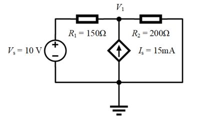
- V1 ist die einzige unbekannte Spannung. Der andere Knoten ist an Masse angeschlossen und wird unser Referenzpunkt sein.
- Der Knoten V1 hat drei Zweigströme:
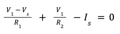
- Der Strom durch Widerstand R1: (V1 - VS)/R1
- Der Strom durch Widerstand R2: (V1 - 0)/R2
- Der Strom durch die Stromquelle In: - Is
- Nach Kirchhoffschem Knotensatz summieren wir sie und setzen sie auf 0:
4. Umschreiben in Form von V1:

Betrachten wir nun mit der Methode der Knotenanalyse einen Stromkreis mit einer Spannungsquelle, die an zwei unbekannte Spannungen angeschlossen ist.
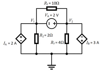
- V1 und V2 haben eine unbekannte Knotenspannung. Der andere Knoten ist an Masse angeschlossen und wird unser Referenzknoten sein, der auf 0 Volt eingestellt ist. Außerdem liegt VA zwischen V1 und V2und ist somit ein Superknoten.
- Der Knoten V1 hat drei Zweigströme:
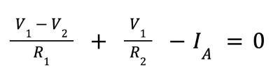
- Der Strom durch Widerstand R1: (V1 - V2)/R1
- Der Strom durch Widerstand R2: (V1 - 0)/R2
- Der Strom durch die Stromquelle IA: - IA or 2 Ampere
- Der Knoten V2 hat vier Zweigströme:
- Der Strom durch Widerstand R1: (V2 - V1)/R1
- Der Strom durch Widerstand R2: (V2 - 0)/R3
- Der Strom durch die Stromquelle Ib: Ib oder 2 Ampere
- Die Gleichung des Superknotens für VA: V2 = V1 + VA
- Nach Kirchhoffschem Knotensatz summieren wir die Stromflüsse für Knoten 1 und setzen sie auf 0:
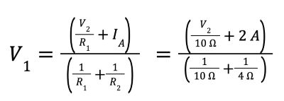
5. Umschreiben in Form von V1:
6. Nach Kirchhoffschem Knotensatz summieren wir die Stromflüsse für Knoten 2 und setzen sie auf 0:
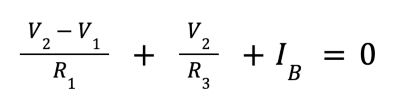
7. Umschreiben in Form von V2.
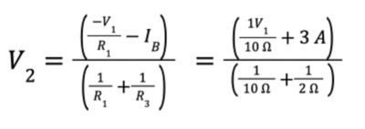
8. Wenn Sie die Gleichung des Superknotens für V2 anwenden und die beiden anderen Gleichungen lösen, erhalten Sie V1 = -7,33 V und V2 = -5,33 V
Erste Schritte zur Knotenanalyse komplexer elektrischer Systeme
Die Knotenanalyse, in der Regel in Form eines SPICE-Solvers, ist ein grundlegender Schritt zur Charakterisierung des Verhaltens eines elektrischen Stromkreises. Von einfachen Schaltungen auf einer Steckplatine bis hin zu den neuesten Halbleitern der Branche mit Millionen von Transistoren müssen Ingenieur*innen Tools wie die Ansys Totem™ Power Integrity Signoff-Plattform verwenden, um nicht nur Spannungen zu berechnen, sondern auch diese Informationen zu nutzen, um Leistungsrauschen zu verstehen und Zuverlässigkeitsfreigaben für analoge Mixed-Signal-Designs zu erzielen.
Die Ansys Twin Builder® Software bietet einen vollständigen Solver für die Knotenanalyse, der mit anderen Tools mit reduzierter Ordnung kombiniert werden kann. Mit ihr können Sie Ihren Stromkreis und dessen Verbindung in Ihrem Produkt analysieren – alles in einer einzigen Schnittstelle.
Hier sind einige Vorschläge für eine effiziente und erfolgreiche Knotenanalyse auf komplexe elektrische Systeme:
- Bevor Sie Ihr Knotenanalysemodell erstellen, verstehen Sie alle Schaltungselemente in Ihrem Design einschließlich ihrer elektrischen Eigenschaften.
- Stellen Sie sicher, dass Ihre Annahmen über Referenzknoten richtig sind, dass sie wirklich geerdet sind und dass die Spannung nicht floaten kann.
- Stellen Sie sicher, dass Sie ein Tool verwenden, das Ihre ECAD-Daten nahtlos lesen kann und nur minimale Benutzereingaben erfordert, um Ihre Schaltungsdarstellung zu erstellen.
- Nehmen Sie sich die Zeit, um die Grundlagen der Knotenanalyse zu verstehen. Verbringen Sie einige Zeit mit Tutorials, die eine einfache Schaltungsanalyse in Bezug auf die Art der Komponenten enthalten, die Sie charakterisieren müssen.
- Verwenden Sie ein Softwaretool, das mehr als nur eine Knotenanalyse durchführt. Verwenden Sie eine Lösung, die die Knotenanalyse eines bestimmten Stromkreises als Ausgangspunkt für weitere Simulationen behandelt.