


DETTAGLI DELL'ARGOMENTO
- Che cos'è l'analisi dei guasti?
- Quando un prodotto si guasta
- Perché i prodotti elettronici si guastano?
- Analisi dei guasti e analisi delle cause principali
- Perché l'analisi dei guasti è importante
- Quali tecniche RCA vengono generalmente utilizzate?
- Come prevenire i guasti prima che si verifichino
- Soluzioni Ansys per l'analisi dei guasti
Che cos'è l'analisi dei guasti?
L'analisi dei guasti, anche nota come indagine del guasto, consiste nel processo di individuazione delle cause che hanno portato a un guasto di un prodotto, al fine di identificare e mitigare la causa principale del guasto. L'analisi dei guasti esamina l'ambiente che ha causato il guasto, il meccanismo specifico che ha portato al guasto e la posizione del guasto.
Per i prodotti elettronici, l'analisi dei guasti isola il guasto in una posizione sul gruppo della scheda di circuiti stampati (PCBA, Printed Circuit Board Assembly), quindi esamina più a fondo i componenti o la posizione della scheda per individuare il sito esatto del guasto.
Quando un prodotto si guasta
Qualsiasi guasto del prodotto richiede un'indagine per identificare la causa del guasto. Sebbene l'isolamento del guasto sia importante, uno dei motivi principali per utilizzare l'analisi dei guasti è evitare che si verifichi nuovamente. Comprendendo i meccanismi di guasto e le cause principali, i produttori possono intraprendere azioni correttive per evitare che gli stessi problemi si verifichino in futuro. I guasti sul campo o i richiami in garanzia sono molto costosi per le aziende, in quanto possono causare ingenti danni finanziari e alla reputazione. Eventuali guasti in fase avanzata sono anch'essi una causa di preoccupazione.
Molti settori utilizzano l'analisi dei guasti come misura di controllo della qualità (QC) durante i processi di produzione o di supporto dei prodotti per identificare eventuali potenziali guasti, determinare la causa principale dei guasti segnalati dai clienti e garantire che i clienti ricevano prodotti di ottima fattura. Tra i settori che conducono frequentemente analisi dei guasti figurano quello automobilistico, aerospaziale, difesa, manifatturiero, biomedico e dei beni di consumo, ma i processi di analisi dei guasti possono essere utilizzati in qualsiasi settore per scoprire come e dove qualcosa è andato storto durante la produzione o sul campo.
Perché i prodotti elettronici si guastano?
I motivi dei guasti dei prodotti elettronici sono molti. In genere non sono il risultato di un problema di progettazione elettrica, ma piuttosto di scelta dei materiali, gestione termica, contaminazione o di problemi di progettazione meccanica. Possono essere dovuti a un carico termico o meccanico che non era previsto o a un carico che era stato considerato ma che ha avuto effetti avversi rispetto a quanto previsto. In altri casi, possono essere dovuti a contaminazione della scheda, a una comprensione parziale delle proprietà dei materiali o del loro comportamento o a un certo livello di corrosione.
Esistono molti modi e meccanismi di guasto diversi che causano guasti a livello di PCBA e singoli componenti. Alcuni guasti elettronici comuni includono:
- Rottura e distacco di fili di saldatura
- Delaminazione
- Rottura del condensatore
- Danno al die
- Problema di interconnessione
- Affaticamento e sollecitazione eccessiva della saldatura
- Frattura del conduttore
- Perdita di corrente indotta da contaminazione
- Migrazione elettrochimica
- Guasto filamento anodico conduttivo
- Cedimento del foro passante placcato
- Cratering del pad o frattura della traccia
Analisi dei guasti e analisi delle cause principali
L'analisi dei guasti e l'analisi delle cause principali (RCA, Root Cause Analysis) vengono spesso utilizzate in modo intercambiabile, ma questo non è del tutto corretto. L'RCA descrive la metodologia generale di risoluzione dei problemi che riguarda il motivo per cui si è verificato un guasto. L'RCA tenta di valutare i fattori che contribuiscono a un guasto e può considerare fattori organizzativi, comunicazioni interne, procedure di progettazione, scarse specifiche, ambiente di utilizzo dei prodotti, ipotesi su scienza dei materiali e molti altri potenziali problemi. L'analisi dei guasti è una categoria di tecniche di raccolta dei dati RCA che si concentra sull'esame sistematico dei dispositivi guasti per identificare la causa principale del guasto e fornire informazioni su strategie di mitigazione che impediranno il guasto in futuro. Le seguenti domande costituiscono la base di un'efficace analisi dei guasti:
- Qual è la modalità del guasto?
- Come si è verificato il guasto?
- Dove si trova il sito del guasto?
- Qual è il meccanismo di guasto?
- Cosa si può fare per evitare che si verifichi di nuovo?
Esistono molte tecniche di analisi dei guasti fisiche e chimiche che possono essere utilizzate per cercare guasti direttamente in un sistema elettronico, tra cui:
- Microscopia a raggi X
- Microscopia acustica
- Microscopia elettronica a scansione (SEM, Scanning Electron Microscopy)
- Microscopia ottica
- Spettroscopia a raggi X dispersiva di energia (EDS)
- Uso di un dispositivo superconduttore a interferenza quantistica (SQUID, Superconducting Quantum Interference Device)
- Termografia
- Test meccanici
- Analisi "dye-and-pry"
- Analisi basata su campionamento trasversale
Le tecniche RCA comuni, come il metodo dei "cinque perché" e Six Sigma, spesso incorporano l'analisi dei guasti come una tecnica di raccolta dei dati per fornire informazioni sulle azioni di mitigazione dei guasti risultanti dalla RCA.
Perché l'analisi dei guasti è importante
I guasti dei prodotti sono spesso nei notiziari e possono avere gravi conseguenze, come ad esempio incendi della batteria di un veicolo elettrico o di uno smartphone. Non solo i guasti dei prodotti sono costosi, ma hanno anche un impatto negativo sulla fiducia dei consumatori.
L'analisi dei guasti consente ai produttori di aumentare la fiducia attraverso azioni correttive e miglioramenti continui dei loro prodotti per soddisfare le esigenze del consumatore. Se un prodotto ha già avuto problemi nell'uso reale, individuare la causa principale e risolvere il problema è fondamentale per assicurarsi che venga messo sul mercato un maggior numero di prodotti.
Ma questo va oltre i produttori stessi. In molti settori, ai produttori vengono forniti componenti provenienti da più origini, quindi i metodi di analisi dei guasti garantiscono tali componenti che siano affidabili e sicuri da utilizzare nel prodotto finale. L'analisi dei guasti garantisce quindi solidità e affidabilità nella supply chain di produzione più ampia, indipendentemente dal settore.
Quali tecniche RCA vengono generalmente utilizzate?
Quando si tratta di stabilire la causa principale del guasto del prodotto, vengono di solito utilizzate quattro tecniche RCA:
Cinque perché: questo metodo analizza la causa e l'effetto di un guasto per comprenderne la causa principale. Inizia con un problema, seguito da una serie di domande di tipo "perché" sul prodotto e sul relativo ambiente fino a quando non viene trovata una risposta.
Diagramma Ishikawa: questo diagramma è noto come diagramma a lisca di pesce per la sua forma finale. Tale strumento presuppone una completa ignoranza dell'ambiente, in modo che gli ingegneri possano valutare altri fattori che potrebbero avere causato il guasto, consentendo loro di restringere il numero di possibili cause fino ad arrivare alla causa principale.
Analisi della struttura ad albero del guasto: un'analisi della struttura ad albero del guasto suddivide un sistema nei relativi componenti e sottosistemi. Esamina la relazione tra il guasto di un sottosistema o di un componente e il resto del sistema per dedurre il percorso del guasto per il sistema di livello superiore. Le analisi della struttura ad albero del guasto esaminano essenzialmente la posizione dei guasti in determinate aree e valutano in che modo influiscono sul sistema più ampio.
Analisi delle modalità e degli effetti del guasto: l'analisi delle modalità e degli effetti del guasto (FMEA) estende l'analisi della struttura ad albero del guasto definendo potenziali modalità di guasto in ciascun nodo e determinando in che modo influenzeranno le prestazioni del sottosistema e del sistema. L'analisi FMEA analizza i guasti fino ai livelli di componente e sottosistema e osserva gli effetti sul sistema più ampio. L'analisi FMEA è più dettagliata dell'analisi della struttura ad albero del guasto (arriva, ad esempio, fino alla perdita di tempo su un chip) ed esistono molti tipi di analisi FMEA con specifiche diverse per settori diversi.
Come prevenire i guasti prima che si verifichino
Sebbene le tecniche RCA tradizionali siano utili, la fisica dell'affidabilità e l'ingegneria dell'affidabilità offrono informazioni più sicure sul motivo per cui si è verificato un guasto del prodotto. Possono essere utilizzate durante qualsiasi fase dello sviluppo del prodotto per fornire informazioni alla RCA e prevenire i guasti prima che si verifichino.
La fisica dell'affidabilità aggiunge un ulteriore livello di precisione all'analisi dei guasti. L'uso di un approccio basato sulla fisica accelera la valutazione delle modalità di guasto e dei meccanismi di guasto eliminando opzioni di guasto ridondanti o altamente improbabili.
Comprendere la fisica del guasto consente agli ingegneri di comprendere in che modo le sollecitazioni meccaniche, termiche, chimiche ed elettriche all'interno di un prodotto possono causare un guasto. Nella maggior parte dei casi, il guasto non è dovuto a fattori elettrici. Al contrario, la maggior parte delle modalità di guasto è dovuta a cause termiche, di selezione dei materiali, di contaminazione e meccaniche (nonché elettriche), che possono essere identificate utilizzando strumenti di simulazione basati sulla fisica dell'affidabilità per evitare il guasto di un prodotto ancora prima della produzione. Ad esempio, il guasto del ciclo termico è un problema comune nei dispositivi elettronici che può essere facilmente mitigato attraverso l'analisi dei guasti.
La combinazione di simulazione e analisi dell'hardware fisico accelera la valutazione del guasto e aiuta gli ingegneri a comprendere la fisica del guasto.
Un tipico approccio di simulazione potrebbe seguire il percorso di una revisione del progetto dei PCBA seguita da un'analisi degli elementi finiti (FEA). I metodi di simulazione valutano i materiali in ingresso e valutano la robustezza meccanica per identificare le modalità di guasto, valutare le possibili modalità di guasto a cui il sistema sarà suscettibile, determinare le soglie di contaminazione ed esplorare le varianti di progettazione che migliorano l'affidabilità del sistema.
Alcuni esempi concreti in cui ciò può essere messo in atto includono:
- Analisi dell'intervallo di temperatura ideale per un composto di riempimento
- Esame dei potenziali meccanismi di degradazione all'interno di una batteria
- Simulazione del sistema di saldatura di un PCBA
- Simulazione dell'impatto di rivestimento conforme sull'affidabilità dei componenti
- Analisi di guasti basati su deformazione, affaticamento e diffusione in base al comportamento fondamentale su scala atomica e molecolare
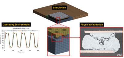
Esempio di case study: Affaticamento della saldatura
Uno dei meccanismi di guasto più comuni dei PCBA è l'affaticamento della saldatura, dovuto al ciclo termico. I moderni PCBA sono una combinazione di molti materiali diversi, tra cui laminati in fibra di vetro, ceramiche, polimeri, stagno, silicio e rame, che hanno proprietà dei materiali ampiamente variabili. Una delle proprietà più critiche da considerare quando si valutano i guasti da affaticamento della saldatura è il coefficiente di espansione termica (CTE, Coefficient of Thermal Expansion).
La saldatura viene spesso utilizzata all'interno di package elettronici per collegare i componenti elettronici alle schede di circuiti stampati, e in genere collega materiali con CTE molto diversi. A causa di cambiamenti nell'ambiente operativo o nella dissipazione di energia dei componenti, i PCBA e i componenti sono sottoposti a un ciclo termico, che provoca l'espansione e la contrazione dei materiali a ritmi diversi. Questa diversa espansione viene assorbita dalla saldatura come deformazione e le tensioni dovute alla deformazione accumulate nella saldatura provocano la spaccatura e, alla fine, la rottura completa della sfera di saldatura.
L'analisi fisica di campioni guasti, utilizzando tecniche quali sondaggio elettrico, raggi X, microscopia a ultrasuoni, sezionamento trasversale con ispezione ottica o SEM e dye-and-pry, può essere molto efficace nel confermare la presenza e la posizione delle crepe da saldatura e il meccanismo di affaticamento della saldatura. Ma quando si tratta di determinare il motivo del guasto e di proporre soluzioni per prevenire ulteriori guasti, la simulazione diventa uno strumento di importanza critica. Con la simulazione, gli analisti possono includere l'influenza di materiali, geometria, ambiente, metodi di fissaggio e altri fattori che possono determinare l'affaticamento della saldatura. I risultati della simulazione forniscono informazioni dettagliate sulla fisica che determina il guasto e consentono alle aziende di testare virtualmente l'impatto di modifiche di progettazione o delle condizioni operative prima di implementare una correzione.
Soluzioni Ansys per l'analisi dei guasti
Sia che si applichino analisi fisica e test o simulazioni alla soluzione di una sfida di analisi dei guasti, la fisica dell'affidabilità è alla base dell'approccio Ansys. Il nostro team Reliability Engineering Services comprende esperti di progettazione per eccellenza, progettazione di sistemi elettronici, imballaggio e produzione che applicano analisi fisica, test e simulazione per risolvere anche le sfide più difficili di analisi dei guasti. Con anni di esperienza nella progettazione elettronica, il team inizia sempre con tecniche non distruttive per identificare le posizioni dei guasti e i meccanismi di guasto.
Il software Ansys è in grado di analizzare molti sistemi elettronici per vedere quali problemi termo-meccanici esistono, o potrebbero esistere, in un prodotto con tecnologia avanzata. La simulazione è una potente aggiunta alle tecniche fisiche di analisi dei guasti e fornisce ulteriori informazioni sulle forze e sui comportamenti dei materiali che potrebbero avere causato i guasti.
Software di previsione dell'affidabilità elettronica Ansys Sherlock™: utilizzato per prevedere guasti basati su problemi termo-meccanici. Il software Sherlock è in grado di simulare il sistema con un guasto nel relativo ambiente nativo per simulare il comportamento che ha causato il guasto. Questo approccio di analisi dell'affidabilità consente inoltre agli ingegneri di identificare i meccanismi di guasto nei componenti, nella scheda e nel sistema per ottimizzare meglio l'ambiente di applicazione previsto. Il software Sherlock effettua previsioni di affidabilità a livello di PCBA e può utilizzare gli input del software Ansys Mechanical™ e della soluzione Ansys Icepak® per simulare l'affidabilità oltre il livello PCBA, ad esempio la modellazione dell'alloggiamento attorno a un PCBA o la creazione di un sistema di raffreddamento che riduce le temperature dei componenti.
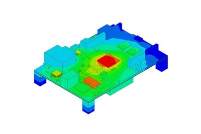
Simulazione di shock meccanici del software Ansys Sherlock
Software FEA strutturale Ansys Mechanical: fornisce simulazioni che tengono conto delle condizioni peggiori in diversi scenari di carico che incorporano elementi del sistema al di fuori del PCBA (ad esempio, alloggiamenti, rinforzi meccanici e altri componenti meccanici di sottosistema di livello superiore). Il software Mechanical può essere utilizzato per ricavare deformazioni della scheda in diverse condizioni di carico in gruppi complessi a livello di sistema. I risultati di un'analisi del software Mechanical possono essere utilizzati per identificare guasti di sollecitazione eccessiva o trasferiti nel software Sherlock per effettuare previsioni di affidabilità a livello di componente a causa di scenari di carico e vincoli complessi.
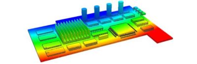
Software di simulazione del raffreddamento di elettronica Ansys Icepak: fornisce un'analisi termica che esamina le temperature di diversi componenti su un PCBA sotto l'influenza di diverse soluzioni di raffreddamento. I risultati delle analisi del software Icepak possono essere utilizzati per identificare le temperature oltre i valori nominali di temperatura dei componenti, valutare i margini di derating dei componenti o essere incorporati nell'analisi Sherlock per previsioni di affidabilità a livello di componente.
Analisi elettrotermica di un scheda di circuiti stampati con il software Ansys Icepak
Ansys ha aiutato oltre 3.000 clienti a identificare e mitigare la causa principale dei guasti dei prodotti, oltre a fornire soluzioni attraverso la simulazione prima che diventino un problema. Se vuoi unirti a una delle oltre 300 aziende che scelgono Ansys ogni anno per risolvere le loro sfide tecniche, contatta oggi stesso i nostri esperti di fisica.