


ANSYS BLOG
June 19, 2023
Using Metamodels of Optimal Prognosis for EMC Analysis
Modern cars — they’re sleeker and faster than ever before, but they’re also more electrified. It’s estimated that the modern vehicle contains up to 1,500 wires, stretching out to about a mile in length. Compare that to the 1950s, when cars had just 55 wires totaling about 50 feet in length. A new challenge now facing car manufacturers today is the complexity of the cable harnesses required to connect all the various subsystems.
A cable harness is a collection of electrical wires typically bound by a material such as rubber, vinyl, string, or a combination of the three. Harnessing cables provides an advantage over loose, dangling wires because the harness provides better protection against adverse effects from vibrations, abrasions, and moisture.
With wire in close quarters inside the harness, it is important to measure the electromagnetic (EM) quality of the cable. A quantitative parameter to estimate the EM quality of a specific cable layout is the crosstalk noise, or the influence on low voltage cables by the high-voltage cables that are in proximity.
To determine the EM quality, a cable needs to be cut up into cross sections. When a cable is measured with just one cross-section, it may test as problem-free. However, cables can move during a vehicle’s motion. As a consequence, multiple different cross-sections need to be tested to diagnose potential electromagnetic interference and compatibility (EMI/EMC) issues. Metamodeling is a technique that can be applied to the design, optimization, and assessment of harnesses. The methodology can be used for automotive purposes, as well as in other industries such as aerospace and defense.
Analyzing Optimization
Robustness analysis has become an important method in the development of industrial products. A computational multiphysics approach lends itself effectively to an automated multidisciplinary optimization process. A framework for numerical optimization can be defined by specifying the design criteria as a set of objectives and constraints. However, one challenge with this approach is efficiently handling the optimization function given all the possible combinations of multiple design parameters. Due to this, a degree of nonlinearity should be considered in the optimization process.
Numerical modeling can simplify the process to evaluate and minimize crosstalk, ensuring high accuracy of the virtual representation of the cable harness and reducing the solution time. A simulation tool can be used to understand which cable parameters (length and location) have the greatest influence. Simulation can also determine the probability that a given cable’s configuration falls below a certain threshold of crosstalk to help synthesize efficient form-factor layouts. By using Ansys Discovery, Ansys EMC Plus, and Ansys optiSLang together, it is possible to understand the impact of uncertainty in the cross-section of the cable based on a metamodel of optimal prognosis (MOP).
A Cable Crosstalk Experiment
To start, a Gaussian distribution, also known as a normal distribution, is used to find the cross sections. This method is a bell-shaped curve that assumes any measurement values will follow a normal distribution with an equal number of measurements above and below the mean. Figure 1 shows the variation in the cross-section of the wires at different locations along the cable.
“Initially, they look the same. Then we use a Gaussian distribution for the cable crossover, and we split it into multiple segments for that one particular wire,” EMA Senior Radio Frequency Engineer Prasanna Padmanabhan says.
This is done for each wire in the cable.
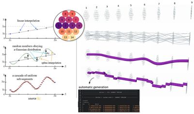
Figure 1. Cross-section algorithm
The implementation and outcome of the cross-section algorithm are seen in Figures 1 and 2. Figure 2 shows the variation in the cross-section of the wires at different locations along the cable.
“So now (in Figure 2), you can see each of the wires within the cable. They are color-coded, and you can see how the wires are getting twisted from one end to the other,” Padmanabhan says. “All these individual lines or cross-sections that you see are all the individual segments.”
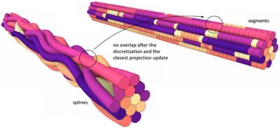
Figure 2. Cross-section algorithm showing the positioning of each wire
Numerical Model
EMC Plus is a finite-difference time-domain (FDTD) solver that can be used to model and simulate cables and transmission lines to identify EMC and EMI problems. Figure 3 shows an automotive cable in EMC Plus with a source box and load box along with a cable cross-section.
“All these cables have the same continuity when you start off because they have the same cross-section as you go from the source all the way to the load,” Padmanabhan says. “But, in reality, what happens is the wires cross over. Because of this, the cross-section changes from one point to the other from the start to the end.”
The dots in Figure 3 represent the beginning or the end of an individual cross-section of the segments on the cable, as well as the wire distribution inside the cable.
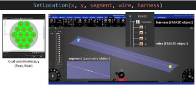
Figure 3. Numerical model in Ansys EMC Plus
Cable Optimization Workflow
To optimize the cable, a parameterization needs to be created for each of the cross sections in each segment. To do that, an application programming interface (API) class was developed to automatically edit the segments’ definition in the input XML file and solve the problem without the user needing to manually edit the configuration file.
In Discovery, users open EMC Plus and call the API to specify the X and Y locations, as well as the segment number, cable number, harness number, and any other parameters associated with it.
“Now the user controls how many combinations they want to be able to simulate,” Padmanabhan said. “They control how the wires cross over within each segment going from point A to point B.”
At every controlled location, a Gaussian and Weibull distribution is applied to discretize the interpolated segments of the wire. Ansys optiSLang reads the EMC Plus project and analyzes its input configuration file. The software then creates all the parameterizations for the segments, cable, and harness. Ansys optiSLang will push through one value at a time for each segment until all combinations have been completed.
“What we can do when we create this many variations is that we can determine what is the worst-case crosstalk,” Padmanabhan said.
Results computed by the voltage probe are defined at the source and load for all the combinations and are shown in Figure 4.

Figure 4. Probe on wire 4 at the source (left) and the load (right)
The histogram response of the probes shows triangular and Gumbel probability distribution functions at the source and load respectively. We get expected results on the source side as the input is a combination of Gaussian and Weibull distributions. Figure 5 shows a Gumbel distribution on the load side. It typically means extreme deviation in the results and is indicative of a potential failure or numerical noise.
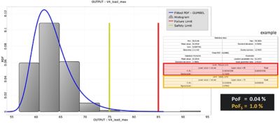
Figure 5. Probability of failure analysis
As a final step, optiSLang can calculate the impact of uncertainty at the source and load based on all designs generated. Figure 6 shows the overall forecast quality by aggregating the effect of discretizing the segments at various locations along the cable.
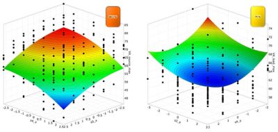
Figure 6. Metamodel of optimal prognosis
Simplify Cable Crosstalk Computation
The complexity of harness layout in a modern vehicle requires the use of efficient numerical methods to analyze the quality of the layout.
Using EMC Plus along with Discovery and optiSLang makes the computation of crosstalk on a cable with nonuniform cross-sections an easy task. A new API was developed to control the cross-section distribution in EMC Plus, and the user only needs to define local X and Y coordinates in the cross-section. The variation of the cross-section along the cable can be controlled by optiSLang. The logic of the variation can be defined in many ways. In the example shown in this blog, controlled splines were distributed in predefined cross-sections driven by a script.
The API can be used to create an unlimited number of combinations for how many sections the cable needs to be broken into, how many wires are in the cable, and how they cross over. This allows the user to find the worst-case EMI scenario and develop an optimal design pattern.
Learn more about how Ansys EMC Plus can help with your projects.