-
United States -
United Kingdom -
India -
France -
Deutschland -
Italia -
日本 -
대한민국 -
中国 -
台灣
-
Ansys is committed to setting today's students up for success, by providing free simulation engineering software to students.
-
Ansys is committed to setting today's students up for success, by providing free simulation engineering software to students.
-
Ansys is committed to setting today's students up for success, by providing free simulation engineering software to students.
-
Contact Us -
Careers -
Students and Academic -
For United States and Canada
+1 844.462.6797

Dynamic voltage drop analysis is a complex process. To perform the appropriate analysis successfully, combinations of many input files and different configuration settings are required.
The switching scenario is key to any dynamic voltage drop analysis. All gates and instances inside the design will not be active at the same time. Additionally, for more complex cells, the possible modes of switching will be numerous. The exact time at which these instances switch can also vary. Many instances near the same location switching at same time or close in sequence can cause local voltage drop hotspots. The switching scenario refers to the data of switching happening in each instance across time. The merit of dynamic analysis depends on the merit of the switching scenario. If the switching scenario can uncover more voltage drop violations in less simulation time, an engineer could more easily improve the robustness of the grid.
There are different ways to create this switching scenario. The obvious way is to rely on data created by doing functional simulation elsewhere. This can be made available via vector files. Although VCD (value change dump) and FSDB (fast signal database) are the file formats available, with FSDB being the most common, we will use the term VCD to refer to both kinds of vector files. Using VCD is a simple and straightforward way to bring in switching scenario information for a dynamic analysis.
However, there are many limitations in doing voltage drop analysis with VCD input. Firstly, procuring VCD is a challenge, as fully fledged, functional simulations are done only toward the end of the design cycle. Voltage drop analysis can't wait that long to get started. Further, VCDs are available for only some of the functional modes and may not be best suited for voltage drop analysis.
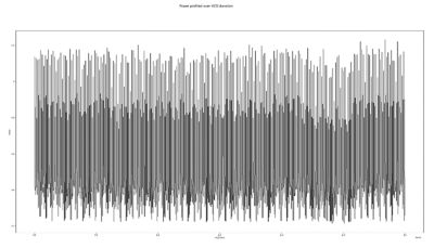
Power profiling over long value change dump (VCD) duration
The majority of engineers doing power integrity analysis prefer to create switching scenarios using vectorless methods facilitated by the software completing the analysis. These vectorless methods provide much flexibility in setup and offer better switching coverage. The shortcoming of such an approach is that a vectorless switching scenario is not an actual functional mode.
This is where register-transfer level (RTL) VCDs come in. These are VCDs available from the front-end design verification side. Compared to gate- or netlist-level VCDs, RTL VCDs are available very early in the design cycle, present for a much longer duration than functional modes, and much easier to procure.
The two key challenges in bringing RTL VCDs into power integrity analysis can be mitigated by the software itself. One is the fact that VCD is from the RTL stage of design, so names would have changed during synthesis. There is a need to do proper name mapping between signals in RTL VCD and pins or nets in a netlist or design exchange format (DEF). This is addressed by doing intelligent name mapping, in which string patterns and common naming changes during synthesis are studied and coded into the power integrity software. Users can also get data from synthesis or formal verification stages and put it in as a name-mapping file.
The second challenge is that events or switching modes are present only for sequential elements in the design, but they need to be propagated throughout the whole design (e.g., combinational logic and a clock tree network). This is also done inside the voltage drop analysis software. These can infer cell functionality and propagate events from flop to combinational. The exact time of events can be derived either from delay propagation or by using the static timing analysis (STA) file input, which would have arrival times for each instance.
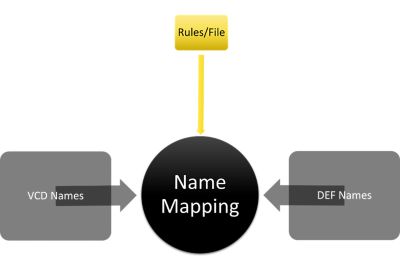
VCD name mapping
The next challenge is not limited to RTL VCDs. In any situation in which VCD is inputted, there is the challenge of selecting a small window from within the VCD duration to do dynamic voltage drop analysis. VCDs, whether they be gate or RTL, can be long: microseconds to even milliseconds. There could be more than one VCD as well. However, transient power integrity analysis is preferred to be done for a much smaller duration, in the nanoseconds range. Thus, there is a need for VCD window selection.
Users usually go with some form of VCD profiling. The most popular method is to go for the VCD window, as it has the highest power. High power would mostly equate to high current, and high current is expected to uncover most voltage drop violation issues. This profiling stage goes through the whole VCD duration and finds out power in small intervals across the VCD. This data is then used to find out the window with the highest power. There are also other advanced ways, like looking for VCD window with highest change in power, looking at region-wise power numbers, or using a combination of the above. Users can also bring in resistance and timing window overlap data to better optimize the VCD window selection process. Depending on time and resource availability, engineers also can opt for doing voltage drop analysis across multiple VCD windows.
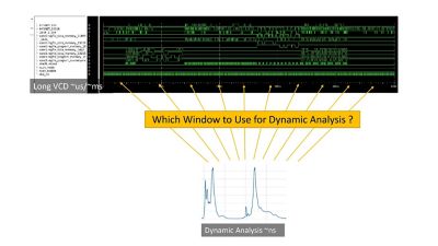
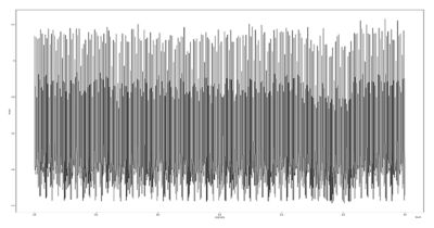
VCD power profiling
Ansys semiconductor chip design solutions, including Ansys RedHawk-SC power integrity signoff platform for digital and 3D integrated circuits (3D-ICs), have been used by many of the top companies in the world for more than 10 years. RedHawk-SC software has mapped names between the RTL and the gate for a countless number of designs across many customers and generations of technology. The platform has continued to improve by adding intelligence and settings/knobs to be able to map more efficiently. As a result, RedHawk-SC software has a very robust name-mapping mechanism.
Similarly, the extensive range of advanced designs it handles and the high quality of challenges it overcomes make RedHawk-SC software especially effective for event propagation. There is also a flow that ensures accurate logic events reflected in the clock network of the design. Since most of the integrated clock gates (ICGs) are inserted into the design post-synthesis, these will not be captured in RTL VCDs. By propagating signals from VCD events at sequential instances, RedHawk-SC software can infer the logic signal occurring at the enable pins of these ICGs. This is then used to gate these ICGs. The ICGs and their downstream clock network will thus have events corresponding to the RTL VCD input.
RedHawk-SC software is built on the Ansys SeaScape cloud-optimized big data analytics platform for electronic design automation. This brings big data analysis to the world of semiconductor design analysis. In addition to enabling distributed compute processing, the Seascape platform empowers users to define new ways to process data and come up with actionable results. This is the future of VCD window selection, in which more data can be combined along with information from power profiling to enable more optimum analysis flows.
RTL VCDs provide an effective solution to the complex aspect of selecting the right switching scenario for dynamic voltage drop analysis. The challenges of enabling this flow include VCD name mapping, propagation of events, and vector window selection. RedHawk-SC software has a robust VCD name-mapping flow and a native solution for doing logic event propagation, as well as an efficient power profiling flow that can be easily augmented with inputs from other data points.
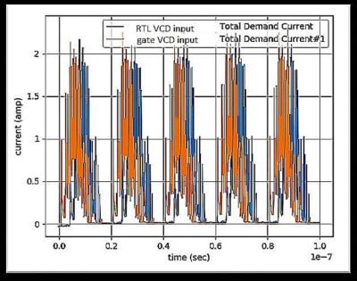
Comparison of demand current from register-transfer level (RTL) VCD input with logic event propagation to a run with equivalent gate VCD input
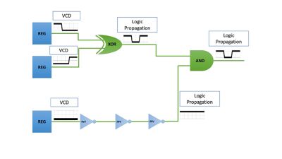
Logic event propagation from VCD signals at registers to rest to design
Learn more about RedHawk-SC software and other semiconductor design solutions from Ansys.
The Advantage Blog
The Ansys Advantage blog, featuring contributions from Ansys and other technology experts, keeps you updated on how Ansys simulation is powering innovation that drives human advancement.


