Case Study
-
United States -
United Kingdom -
India -
France -
Deutschland -
Italia -
日本 -
대한민국 -
中国 -
台灣
-
Ansys is committed to setting today's students up for success, by providing free simulation engineering software to students.
-
Ansys is committed to setting today's students up for success, by providing free simulation engineering software to students.
-
Ansys is committed to setting today's students up for success, by providing free simulation engineering software to students.
-
Contact Us -
Careers -
Students and Academic -
For United States and Canada
+1 844.462.6797
“This optimization of airflow through our Meditate Air Purifier could not have been done without CFD simulations because there were so many interconnected parameters to understand. Ansys Fluent helped us to monitor the airflow in all three stages of the purifier and adjust the design until we had optimal flow conditions in each segment.”
— Ashit Kumar
Senior Manager, Computational Fluid Dynamics (CFD) Simulation, Havells India Ltd.
Havells India Ltd. decided to enter the air purifier market to help solve the problem of unacceptably high air quality index (AQI) values, which are frequently greater than 100 in parts of India. They designed the Meditate Air Purifier to be a high-performance, aesthetic addition to any room, with advanced features like a titanium dioxide (TiO2) photocatalytic module to break up volatile organic compounds (VOCs). To help them solve design challenges, they used Ansys computational fluid dynamics (CFD) simulations to ensure that airflow through the three stages of the purifier — the case and high-efficiency particulate absorbing (HEPA) filter, the blower, and the TiO2 module — was optimized for maximum purification capabilities.
Challenges
While it may initially seem like moving the largest volume of air through the purifier unit is desirable to clean more air quickly, each of the three stages of the purifier has requirements that make this unrealistic. The pressure drop in the HEPA filter, the noise generated by the spinning rotor in the blower, and the required residence time of the VOCs on the TIO2 catalyst surface all had to be optimized using one flow rate throughout the device.
Engineering Solution
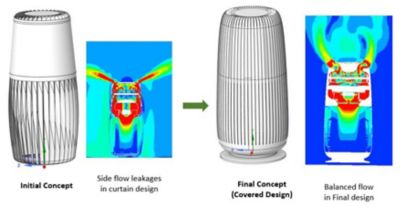
In the initial design of the outer casing (see Figure 1), the simulation showed that some of the air escaped out of the sides of the purifier unit before reaching the top catalytic purifier unit. In the revised covered design, the HEPA filter (the cylindrical-shaped blue element at the bottom of the simulation images) was made thicker at the bottom and sides. Fluent simulations showed that all airflow remained inside the purifier, exiting from the jets at the top after all purification had been completed?

Figure 1. CFD simulations of the initial design and the final covered design of the outer casing. The HEPA filter is the cylindrical-shaped blue element at the bottom in the simulations.
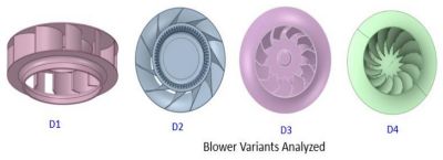
Havells engineers looked at four blower designs and the flow patterns they caused through the purifier using Fluent. The design with the best flow pattern and velocity for delivering the air to the catalytic module was too noisy. Eventually, through a process of iteration, Havells chose an alternative design that delivered the optimal balance of flow velocity, flow location, and noise level

Figure 2. The four blowers investigated by Havells engineers
The catalytic unit consists of parallel fins of a substrate containing the TiO2 particles. Originally, Havells engineers arranged these fins in a circle with all fins at a 90-degree angle to the blower; that is, they were standing straight up. But the flow was not optimal with this design. By tilting the fins inward at an angle, they improved flow intake through the module and achieved the desired flow velocity range.
Benefits
Using Fluent simulations, Havells engineers achieved the optimal airflow for all three stages of their Meditate Air Purifier, balancing the conflicting demands of pressure drop, noise, and residence time in the TiO2 module for optimal air purification.
See What Ansys Can Do For You
See What Ansys Can Do For You
Contact us today
Thank you for reaching out!
We’re here to answer your questions and look forward to speaking with you. A member of our Ansys sales team will contact you shortly.


