


ANSYS BLOG
November 15, 2023
Freudenberg Brings e-Power Solutions to the Maritime Industry
Could an onboard hydrogen-supplied fuel cell system be the decarbonization tool the maritime industry has been searching for?
The engineers at Germany’s Freudenberg e-Power Systems believe they have delivered that very solution.
The Freudenberg Group, which manufactures a variety of industrial technologies and products, has turned its attention to creating a scalable, carbon-neutral power and propulsion system for marine vessels — which are some of the transportation industry’s biggest greenhouse gas emitters — with 2022 founded Business Group Freudenberg e-Power Systems (FEPS).
Their innovative concept for more independency from fossil fuels for the heavy-duty industry comes in the form of a compact onboard chemical plant: a hydrogen-generation module that converts methane or methanol to supply hydrogen to a stack of low-temperature polymer-electrolyte membrane fuel cells (PEMFC). A single system produces a net output of 500 kW of electricity and multiple systems can be combined to meet the ship’s energy demands.
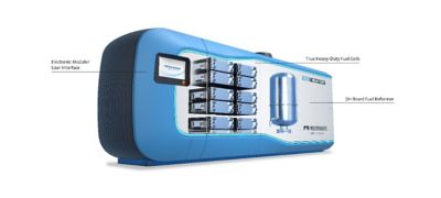
Figure 1: Overview of Freudenberg’s maritime PEM fuel cell system. The system includes the hydrogen generation module, the fuel cell module, and the electronic module. The hydrogen generation module is a chemical plant which converts Methanol or Methane to hydrogen-rich reformate. The hydrogen-rich reformate is supplied to the fuel cell module. The fuel cell module includes several heavy-duty fuel cell stacks which produce electricity by the electrochemical reaction of hydrogen and oxygen inside the fuel cells. The electricity is supplied via the electronic module to the ship. © Freudenberg e-Power Systems
Engineers used Ansys Fluent, Ansys nCode Design Life, and Ansys Mechanical to model the plant’s fuel cells, reactors, and other components. They also used Ansys Cloud Direct for high performance computing (HPC), which was especially useful given they were performing multiscale simulations.
According to Stephanie Frankl, Ph.D., Engineer System Simulation at Freudenberg, simulation helped the team tackle the essential tasks of maximizing hydrogen generation, extending the fuel cell’s lifetime and optimizing component durability.
Not only did simulation enable those activities, but it also provided an important time- and cost-saving benefit: reducing the number of design iterations needed before prototyping.
More Business, More Problems
Between ferrying raw goods from one port to the next and bringing finished products back again, more than 80% of the world’s merchandise trade goes by sea. That means global shipping is a big business and it’s growing post-pandemic: the global container fleet is expected to increase by 6.3% this year and by 8.1% in 2024.1
While that may be positive economic news, it comes at a steep environmental price. The global shipping industry produces about 2.8% of all greenhouse gas emissions annually2, and that doesn’t include cruise ships, which are more carbon-intensive than any other kind of ship. The fear is that as the volume of shipments (and passengers) increases, emissions will, too — even though the International Maritime Organization (IMO) has set an ambitious goal of reaching net-zero greenhouse gas (GHG) emissions from international shipping close to 2050 along with a commitment to ensure an uptake of alternative zero and near-zero GHG fuels by 2030.3
But as both the maritime and cruise industries note, it will take technological ingenuity to close the gap between goals and reality, and no one is wasting any time tackling the problem. In an all-hands-on-deck approach, everyone from industry advisers to the European Maritime Safety Agency has been studying alternatives to conventional internal combustion engines for propulsion and onboard power. Since 2016, the focus has been on fuel cells, and while several types have been considered, the consensus is that low-temperature PEMFCs, which require only hydrogen and oxygen to produce electricity, hold the most promise for the shipping sector.
Engineers at Freudenberg e-Power Systems have built upon the strengths of PEMFCs while also taking aim at one of the biggest roadblocks to using them on vessels: storing huge volumes of hydrogen without taking up too much precious cargo space.
A Novel Approach
Using low-temperature PEMFCs for transportation applications isn’t new — they’ve been generating power for heavy-duty trucks and buses for some time and are prized for being compact in design and capable of high energy densities, meaning they can store a lot of energy in a small amount of mass. Because they operate at temperatures lower than 100°C, they can also start up quickly.
The key incentive for using PEMFCs on ships, though, is that they produce power through a chemical reaction between oxygen and hydrogen without releasing any harmful emissions. To do that, of course, requires both oxygen and hydrogen, which brings up one of the challenges of the approach: to store enough hydrogen onboard to meet the power or distance requirements of marine vessels.
While it’s easy enough to capture oxygen from the environment, hydrogen can’t be pulled out of nowhere. Instead, it must be separated from the other elements in the molecules where it occurs, then stored in liquid state or as a highly compressed gas. Either way, because of hydrogen’s comparably low volumetric energy density — it takes up a relatively large volume for a given amount of energy stored — storing a sufficient volume onboard would likely require multiple huge bunkering tanks that could squeeze stowage.
The Freudenberg solution uses a compact steam reforming plant to convert green methane or methanol — which is easy to transport, handle, and store — into hydrogen. Nearly half of the world’s hydrogen production comes from steam reforming. It’s considered the state-of-the-art method.4 The overall reaction inside the fuel cell is identical to the direct combustion reaction in an internal combustion engine, only without producing nitrogen oxide emissions. Instead, the chemical energy stored in the fuel is directly converted into electrical energy with only water vapor emitted.
Of course, a rudimentary knowledge of organic chemistry tells you that there’s a lot of carbon in methane and methanol, which begs the question, how is this a net-zero process? As FEPS’ engineers point out, when methane and methanol are produced from green hydrogen, any CO2 that’s released was captured before in the production process, so there’s a closed loop for CO2. In other words, the source of the constituent products matters, and that’s something Freudenberg has taken into consideration.
Decades to Go
To develop their onboard plant, Freudenberg engineers didn’t have to totally reinvent PEMFC technology. But they did have to create a fuel cell that could last the decades a seafaring vessel is in service — far longer than fuel cells for automotive applications.
This is where Fluent and its powerful meshing capabilities came in.
Fuel cell lifetime depends on a number of variables, but component design and operating conditions are key to developing a product that can go the distance. Extending the lifetime of each fuel cell component means taking into consideration countless individual requirements. For example, the fuel cells have to have a homogenous distribution of reactant gases across them; for the polymer membrane, homogenous temperatures are required.
Fluent simulation enabled engineers to visualize and investigate the influence of operating conditions on species, temperature, and current distribution inside the fuel cell.

Figure 2: Temperature distribution inside the membrane of the fuel cell simulated and postprocessed in Ansys Fluent. Blue indicates low temperatures, red indicates high temperatures. © Freudenberg e-Power Systems
The work involved creating a computational domain by combining two meshes with a total mesh count of more than 50 million cells. Victoria Damerow, Freudenberg Fuel Cell Engineer, said meshing was particularly important for the fuel cell simulation because of how complex the geometry of the fuel cell model is.
“The complexity is caused by the fuel cell's multi-scale characteristic since the fuel cell geometry includes components in the cm range — for example, the bipolar plates — but also components in the micrometer range, for example, the membrane-electrode-assembly,” Damerow said.
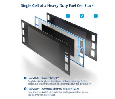
Figure 3: Single cell assembly of Freudenberg's PEMFC including two bipolar plates and the Membrane-Electrode-Assembly (MEA). The bipolar plates guide the flow of reactants to the MEA. © Freudenberg e-Power Systems
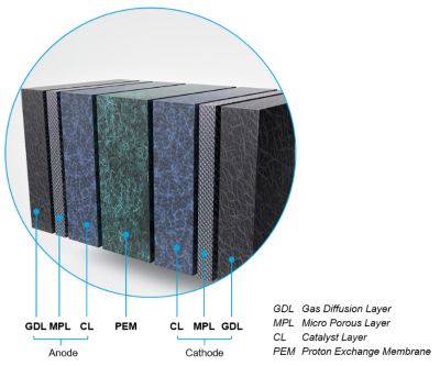
Figure 4: Structure of the Membrane-Electrode-Assembly (MEA) of a PEMFC. The MEA consists of the porous anode and cathode electrode and the proton exchange membrane (PEM). The membrane is made of polymer which is electronically non-conductive and thus isolates the anode from the cathode side. However, the polymer is capable to transfer protonic charges from the anode to the cathode side which is required to enable the electrochemical half-cell reaction of hydrogen and oxygen in the anode and cathode catalyst layer (CL). The electrodes also include the gas diffusion layer (GDL) and microporous layer (MPL) which distribute the gaseous reactants to the catalyst layers. © Freudenberg e-Power Systems
“The fuel cell's geometry includes both very thin and noticeably larger components. Consequently, creating a mesh with sufficient resolution and quality across scales, while also keeping computational costs manageable, is a big challenge for us,” Damerow said. “Ansys offers a range of meshing tools, and we selected the ones that fit the needs for the respective fuel cell components best. By combining the different meshes we achieved a very good overall result. So, the flexibility of the Ansys meshing tools is highly advantageous for this use case."
Fluent also helped engineers optimize the system efficiency by maximizing hydrogen generation through better methane or methanol conversion and improving the heat recovery.
“We have to optimize the flow within our reactors to get the best fuel conversion possible because this defines the efficiency of the system,” Frankl said. “In addition, we have to include heat integration in the process in order to optimize our heat recovery. And we model all that's going on within our catalysts that we use for the steam reforming.”
Frankl noted that they use the same dual-mesh approach for reactor development that was used in fuel cell modeling.
“It's really convenient that you can use different tools to build the optimal mesh for each part,” Frankl said. “And then Fluent is very good in combining all those different meshes into one, resulting in a very good simulation where all parts that require high resolution are well-resolved and the other parts that are not that important can have a coarser mesh in order to save some computational effort.”
Ship Shape
Fitting a fully functional chemical plant into the space constraints of a cargo ship or other vessel isn’t like creating a scale model of a full-size facility.
For the FEPS engineers, working with a small footprint meant more than just shrinking the size of the hydrogen-supply module but also coming up with what they called “very creative reactor shapes” that the ship’s space could accommodate.
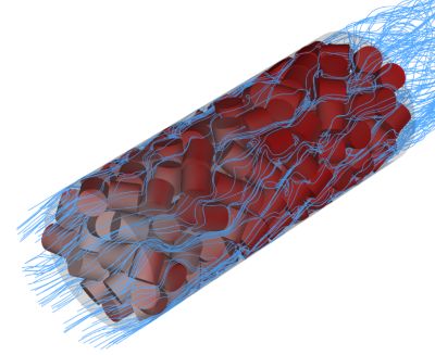
Figure 5. A simulation of a random packing of cylinders in a reactor bed created using Ansys Rocky, showing the gas flow streamlines. In this simulation, the temperature at the wall of the tube containing the packed bed was fixed, and heat transfer from the wall to the fluid, across the packed bed, was evaluated. The final aim of the simulation was to validate a custom heat-transfer model of the porous media approach to packed bed simulations. © Freudenberg e-Power Systems
They also had to weigh how storms or strong waves might create vibrations or accelerations that could affect the plant’s structural strength.
Using Mechanical to model the effect of operating conditions on different components allowed engineers to balance size and shape with efficiency and effectiveness, ensuring that an unconventionally shaped facility could withstand those natural forces while also meeting certification requirements. By pairing Mechanical with nCode Design Life, the industry’s leading tool for durability analysis, engineers could comprehensively analyze fatigue, identify potential weaknesses at the component level, and better predict the plant’s operational life.
Smoother Sailing
Once engineers had completed the models for the fuel cell and hydrogen-supply modules, they combined them to model the behavior of the entire system. The next step was to verify and validate the simulations and then use measurement data from an initial prototype to increase model accuracy and reliability.
Through this virtual development process, Freudenberg e-Power Systems has made a literal sea change in sustainable maritime performance, answering the call from business and society for a lower-emission way to get goods and people from point A to point B.
Considering the increase in popularity of vacation cruises and the expanding reliance on freighters for global trade, these advances in PEMFC technology should bring some welcome relief to international waters — and to the atmosphere.
For an industry determined to participate in the green mobility movement, Freudenberg's hydrogen-supplied power unit is likely to mean smoother sailing for years to come.