-
United States -
United Kingdom -
India -
France -
Deutschland -
Italia -
日本 -
대한민국 -
中国 -
台灣
-
Ansys is committed to setting today's students up for success, by providing free simulation engineering software to students.
-
Ansys is committed to setting today's students up for success, by providing free simulation engineering software to students.
-
Ansys is committed to setting today's students up for success, by providing free simulation engineering software to students.
-
Contact Us -
Careers -
Students and Academic -
For United States and Canada
+1 844.462.6797
ANSYS BLOG
October 25, 2023
What is Design Failure Mode and Effect Analysis (DFMEA)?
Design failure mode and effect analysis (DFMEA) is a process that helps engineers understand the impact of potential risks associated with a design. Introducing FMEA in the design phase is a best practice that helps answer questions like:
- What might go wrong with a design?
- What are the consequences of a specific type of failure?
- How obvious will the failure be to the user?
- How is the failure detected?
- How can we mitigate the effects of a failure on product reliability or safety?
- How can we prevent failure in the first place?
What is Failure Mode and Effects Analysis (FMEA)?
To understand what DFMEA is, we must start with a clear understanding of failure mode and effects analysis (FMEA). FMEA is a systematic approach to recognize and evaluate potential failures of systems, products, or processes. FMEA identifies the effects and outcomes of failures or actions and helps product developers eliminate or mitigate the impact of failures.
Every product has modes of failure at different levels of integration, from component to system and everything in between. Each failure mode leads to potential impacts on the efficacy, reliability, and safety of the product and presents challenges of detection, mitigation, and prevention. FMEA is a tool that helps address those challenges by:
- Identifying the failure risks associated with a product design.
- Establishing an action plan to reduce risks with highest impact.
- Ensuring accountability and traceability of the actions by risk reduction.
First developed in the late 1940s by the U.S. military, FMEA techniques were adopted by NASA in the 1960s and later by the automotive industry in the 1970s. Throughout the 1980s, efforts led by the automotive industry helped consolidate and standardize FMEA best practices to optimize the approach as a quality improvement and risk assessment tool at various stages of product development. Today, major industries such as energy and healthcare, in which high reliability and product safety are critical considerations, have adopted the practice of FMEA to meet industry standards (e.g., SAE J1739-FMEA) for supplier and product qualifications.
DFMEA vs. FMEA
FMEA is broadly divided into design and process approaches, depending on whether it is applied toward a design of a system/product or a process/workflow. This article focuses specifically on FMEA of a design, which is known as DFMEA.
What Industries Use DFMEA?
While DFMEA is valuable in any design process, it is especially critical in industries in which the pace of new product introduction (NPI) and new technology integration is high. New products and technologies inherently have little to no failure history. While assessing similarity to previous products or technologies can be useful, a disciplined approach to identifying likely failure modes and mechanisms based on reliability physics principles and the DFMEA process is critical to risk mitigation. Failure to make DFMEA a critical design-stage tool can result in costly failures showing up in production, qualification testing, or even in the field.
DFMEA helps product teams understand the potential failure modes of designs early in product development so that they can be designed out. It enables the impacts of those failures to be mitigated through elements of the design, methods of detection, or the overall operational and logistics support concept for the product. Some of the industries that have embraced the DFMEA concept include:
- Automotive
- Aerospace
- Defense
- Industrial
- Manufacturing
- Healthcare
- Software
Learn the Purpose and Benefits of DFMEA in Product Development
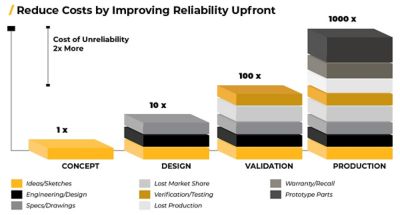
DFMEAs can be used throughout the product life cycle, from prototype design until the production phase. The primary objective being detection of potential failures impacting reliability or safety before going to production. Costs of unreliability of a product can be significant, and it increases exponentially the later it gets detected in the product life cycle, as estimated in Figure 1.

Diagram showing how the cost of preventing reliability problems increase later in the product life cycle
Understanding the DFMEA Process
Although the DFMEA process requires certain key resources and time commitments, it is straightforward compared to many other reliability assessment methods that require complex statistical analysis and interpretation. To get maximum benefit from the DFMEA process:
- Remember that DFMEA is not a one-time exercise, so conduct the analysis early and throughout the design process. The initial DFMEA sets actions required to mitigate risks identified in the design at that time. As significant design changes occur, the DFMEA should be updated to reflect the most current risks and mitigation/prevention strategies.
- Work as a team. Include participants from disciplines that represent the full product development, deployment, and support process (e.g., design, manufacturing, test, and logistics support). Each of these disciplines brings different perspectives and experience to the process, and a diverse team gives the best chance of identifying failure modes and the most effective mitigation and prevention strategies.
- Use a facilitator. The facilitator is not expected to be an expert in product design, but rather an expert in the DFMEA process. Ultimately, the facilitator’s role is to properly scope the DFMEA and drive the process to conclusion, with detailed documentation of the team’s work and definition of the key actions required to implement the risk elimination and mitigation strategies developed.
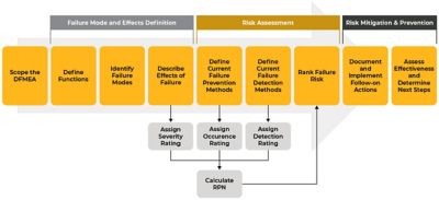
Although the detailed steps of a DFMEA may vary slightly from standard to standard, the core processes of any DFMEA are scoping, failure mode and effects definition, risk assessment, and risk mitigation (Figure 2).

The DFMEA process helps identify, assess, and mitigate the risk of unexpected product failures.
Scoping of DFMEA
The scope of a DFMEA addresses the level of detail to be considered. For example, a DFMEA scoped at the component level considers failure modes and risk mitigation strategies for each component in the design. A component-level DFMEA might consider failure modes like short, open, loss of capacitance, or high leakage current for a capacitor.
While component-level DFMEAs can be useful, extending the results of component-level DFMEA to system-level impacts and risks is more difficult. As an alternative, a DFMEA can be scoped to the subsystem or even the functional block diagram level. Doing so allows the analysis to begin at a much earlier stage of the design and establishes a baseline for DFMEAs with more refined scopes as the design progresses.
Failure Mode and Effects Definition
With the scope confirmed, the initial work of the DFMEA team focuses on breaking down the system (consistent with the scope definition), identifying the potential failure modes of each part of the system, and identifying the effect of each mode on the function of the product as perceived by the user. For example, if a user turns a power switch to the “ON” position and the corresponding indicator light does not turn on, the user might state the failure mode as, “Indicator light does not turn on.” The effects of this failure could be stated as, “Inaccurate indication of power-on state” or “High voltage hazard to user due to inaccurate indication of power state.” Each failure mode can have multiple effects and should be considered carefully from all perspectives on the DFMEA team.
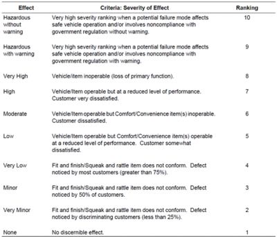
Ultimately, the team will quantify the severity of the failure based on the most severe effect by using a numerical severity rating or index (usually between 1 and 10), reflecting the impact on product performance perceived by the user. The DFMEA team should agree on the rating scale to be used prior to initiating the failure definition process. Figure 3 shows an example rating scale given in the SAE J1739 standard.

Figure 3. SAE J1739, “Guidelines for Severity Ranking”
Risk Assessment
The goal of risk assessment is to quantify the overall risk of a failure in terms of severity, probability of occurrence, and the ability to be detected. As you might suspect, severe failures that are likely to occur and hard to detect present the highest risk. Minimally severe failures that are not likely to occur and are easy to detect receive the lowest risk ratings.
The risk rating is a weighted factor called the risk priority number (RPN), and it is used to rank failure risk from highest to lowest. As with definition of severity, defining the probability of occurrence and likelihood of detection requires input from members of the DFMEA team with a broad range of experience across the product life cycle. With the help of the facilitator, a DFMEA team should establish common probability of occurrence and detection definitions and a rating scale before getting into the definitions of failure.
Risk Mitigation and Prevention
The final phase in the DFMEA process is concerned with risk mitigation and prevention through execution of a control plan. The control plan details the areas of ownership and accountability, as well as a timeline of completion for each individual prevention or mitigation task. With changes in product design, characteristics, and specifications, actions taken are updated to determine the new risk rating with implemented changes. This process serves as a communication tool for both upstream and downstream supply chain groups to ensure the potential risk factors are not only identified, but also eliminated or reduced.
Example DFMEA and Template
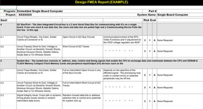
A major telecommunications products company for defense and military requested that Ansys Reliability Engineering Services (RES) team facilitate a DFMEA analysis on a printed circuit board assembly (PCBA) for a next-generation GPS product. The RES team scoped and facilitated the analysis at the block level, taking into consideration all components that make up the circuit of each block.
A team representing design, production, supplier quality, and supply chain management performed the analysis. Based on the established ranking and threshold criteria, key risk factors were identified. Based on experience with similar systems, the RES team also contributed to opportunities for improvement in the design, including PCB manufacturing guidelines and best practices to ensure high reliability, selection of the right quality grade for components, and protection strategies to mitigate electrostatic discharge and electrical overstress (ESD/EOS) failures.

Figure 4. Example of a DFMEA documentation template
The customer followed through on the control plan, which resulted in significant cost savings and prevention of field failures by implementing second-level interconnect improvements at board level, as well as adopting external protection techniques to mitigate ESD and EOS failures in the field.
Contact
If you have an impending product launch and are looking to assess reliability of the product and are unsure of the potential risks prior to manufacturing, please submit your request here or contact the Ansys Reliability Engineering Services Sales team at 301-640-5831 to schedule a session to discuss opportunities.


