


Let’s agree that it’s always good to know where you are when you are airborne. The problem is that, in fact, precisely where you are may not always be known. Modern airframes, whether they be planes moving people from one location to the next or drones delivering packages for Amazon, determine location in real time using radio frequency (RF) signals beamed from the Global Navigation Satellite System (GNSS). However, the five satellite networks that constitute the GNSS hover some 20,000 km above the surface of Earth, and the signals reaching the antenna on an airframe are very weak. If a plane flies through an area where a stronger RF signal creates interference — intentionally or unintentionally — the weak GNSS signal can be lost. Until it clears the interference, the navigation system may not be able to calculate the airframe’s actual position — which would be a serious problem if the signal were lost, say, just as a plane was descending to land on a foggy runway.
You could try to overcome this problem by documenting a specific flight path and recording where and why the GNSS signals were lost, but the problems with this approach are manifold. Not only would it be inefficient and expensive to explore every common flight path, but some signal loss might be caused by antenna design, which might affect only aircraft using that antenna. Additionally, some signal losses experienced by the aircraft might be caused by transient sources on the ground, such as a long-haul trucker who employs an illegal jammer to prevent a toll gate from tracking the truck’s position. Thankfully, researchers at the German Aerospace Center (DLR) have found a far more elegant, cost-effective way to address the problem of signal disruption and loss of position insight using simulation tools from Ansys.
Predicting Real-life Outcomes Without Actual Flights
In their paper “Virtual Validation of In-Flight GNSS Signal Reception During Jamming for Aeronautics Applications,” authors Veenu Tripathi and Stefano Caizzone describe their work developing an approach to ensuring uninterrupted GNSS reception, one that ultimately avoids the need to conduct costly flights to determine where and why GNSS signals might be lost. Using Ansys HFSS electromagnetic simulation software and Ansys Systems Tool Kit (STK) digital mission engineering software, Tripathi and Caizzone developed a digital twin that reconstructs an entire flight scenario (including flight dynamics, the antenna actually used on the airframe, and the impact of its installation on aircraft) and uses simulation to predict signal reception and interference. They demonstrate the ability to use simulation to analyze the in-flight performance of different antenna-aircraft configurations to overcome specific interference scenarios.
The project undertaken by Tripathi and Caizzone involved successive phases to testing and validation. Initially, they used HFSS software to design a compact (3.5 inch) antenna array consisting of five elements (four focusing on the L1/E1 GNSS transmission bands and one focused on the L5/E5a band). The antenna then was built and tested in a semi-anechoic near-field chamber at the DLR, where the resulting electromagnetic fields were measured and converted to equivalent currents that would be used in later simulations. Subsequently, Tripathi and Caizzone used HFSS software to combine the mesh of the antenna with a computer-aided engineering (CAE) model of a plane. This not only enabled the researchers to see how reflections from the plane might affect the radiation patterns of the antenna but enabled them to build a digital twin of the actual plane and antenna they would use to validate the results of their flight simulations.
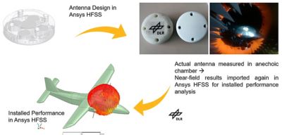
Veenu Tripathi and Stefano Caizzone used Ansys HFSS electromagnetic simulation software to combine the mesh of an antenna with a computer-aided engineering (CAE) model of a plane they would later use to validate the simulated performance of the antenna in flight.
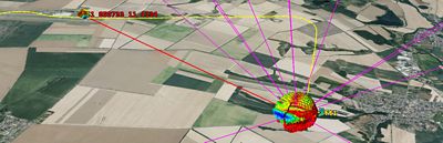
Tripathi and Caizzone also used the facility at the DLR to measure the performance of an antenna that would be used to send a GNSS jamming signal in the path of a plane. They then imported that performance information, along with information about the performance of the plane and antenna combination, as well as the downlink signal characteristics of the GNSS satellites operating in the L1 and E1 RF ranges, into STK software. Because the STK solution is designed to support digital mission engineering and systems analysis, it provided Tripathi and Caizzone with the power they needed to construct a complete simulation of an aircraft encountering a GNSS jamming signal in flight.
Validating the Simulated Results
To validate the performance results of their antenna in simulation, Tripathi and Caizzone did fly a plane with their HFSS-designed antenna over a test course. They measured the actual in-flight performance characteristics of the four antennas in their array both in the presence and absence of interference from the GNSS jamming source. Subsequently, they compared the real-world measurements with those produced in simulation using the HFSS and STK solutions and found good agreement between the datasets.
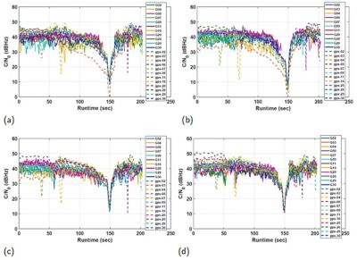
Measured versus mission-calculated carrier-to-noise ratio data for connectivity from each of the L1/E1 antenna elements to each of 11 different GNSS satellites in the presence of a jammer signal. (a) Ant.1. (b) Ant.2. (c) Ant.3. (d) Ant.4. Solid lines = measured results; dashed lines = simulated results. “G#” and “gps-#” identify the GPS satellite source.
“By incorporating actual antenna measurement and installed performance analysis into the system flight scenarios,” the researchers write, “we can gain valuable insights into the performance to be expected in flight, even before flying. This approach allows for a more realistic representation of the conditions and parameters involved, enabling better insights and predictions for the test outcomes and saving a lot of time and money needed for multiple actual flight trials. This showcases the tool’s significant capability as a predictive tool, enabling the planning of experiments or even virtually simulating various antenna (and) aircraft configurations while operating in specific interference scenarios to obtain results that closely approximate actual flight conditions.”
Visit Ansys at Booth No. 345 at the AUSA 2024 Annual Meeting & Exposition in Washington, D.C., from Oct. 14 to 16.
Just for you. We have some additional resources you may enjoy.
Citation: Tripathi, V.; Caizzone, S., “Virtual Validation of In-Flight GNSS Signal Reception During Jamming for Aeronautics Applications,” Aerospace 2024, 11, 204. https://doi.org/10.3390/aerospace11030204
“By incorporating actual antenna measurement and installed performance analysis into the system flight scenarios, we can gain valuable insights into the performance to be expected in flight, even before flying.”
— Veenu Tripathi and Stefano Caizzone, researchers, German Aerospace Center