


Over the past decade, additive manufacturing (AM) technologies have been rapidly emerging, revolutionizing manufacturing processes and offering unprecedented opportunities for innovation and efficiency. AM has shattered the constraints of traditional manufacturing methods and empowered the creation of sophisticated designs while significantly reducing lead times.
Qualifying metal parts produced by AM, particularly those made via laser powder bed fusion (LPBF) or electron-beam manufacturing (EBM), presents significant challenges due to the costly and time-consuming nature of experimental iterations. Qualification is crucial, especially in critical industries such as aerospace and biomedical, in which stringent reliability and safety standards must be met. Like other manufacturing processes, parts produced by LPBF, for instance, may exhibit defects such as porosity, and heterogeneous microstructures, which directly impact strength and reliability. Lack of fusion porosity, for example, is one of the main causes of reduced fatigue strength of AM parts. Moreover, these defects can vary within a single part when printed using different build setups, process parameters, or orientations — a complexity that would be prohibitively expensive to resolve through trial and error alone.
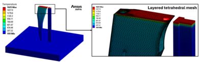
Figure 1. Thermal simulation results in Ansys Mechanical structural finite element analysis (FEA) software showing the layer tetrahedral mesh capturing the part’s curvatures and the voxel mesh used for the support structure.
Enhancing LPBF Part Qualification With Simulation Techniques
The interest in qualifying LPBF parts using finite element analysis (FEA) or other modeling techniques has been evident for several years now. Previous efforts focused on simulating the process at both the microscale to understand melt pool behavior within limited domain and the macroscale to predict final distortions and residual stresses. These simulations aided in optimizing process parameters, achieving desired melt pool sizes, and implementing distortion compensation techniques to attain as-designed parts. Yet, the ability to predict part-scale micro defects and properties remains severely limited.
The simulation of the LPBF process can enhance part quality and reliability within hours or even minutes. Ansys prioritizes aiding companies in qualifying AM parts through rapid part-scale simulations, reducing costs linked to failed builds, energy, and materials. Firstly, Ansys has developed the layered tetrahedral meshing (LTM) capability within Ansys Mechanical structural FEA software, enabling the accurate capture of complex geometrical features. Secondly, by establishing a workflow from microscale to macroscale, Mechanical software facilitates an understanding of defect origins. Simulation outcomes offer expert insight into optimal orientations, overheated zone locations (hotspots), microstructural disparities, and pore formation determinants. These insights can also enable the mitigation of defect mechanisms by changing process parameters in critical regions to more appropriate settings.
Heat Accumulation in LPBF: Influencing Part Qualification
In LPBF, alongside selecting process parameters, heat accumulation serves as a main determinant for evaluating process behavior and defects. Thermal histories may diverge across different locations within a part. Certain areas of a part may exhibit residual heat effects, leading to overheating and consequently resulting in unexpected process behavior, manufacturing defects, and variation in mechanical properties.
In Figure 2, hotspots are evident within the center of an inverted cone part (the single part on the plate). These hotspot areas experience high heat accumulation, leading to elevated predeposition temperatures (i.e., the temperature before scanning the subsequent layer) and reduced cooling rates. These observations yield valuable insights for addressing this variable behavior through corrective actions to qualify parts faster. For instance, adjusting the power value at these critical layers to a lower setting can prevent manufacturing defects arising from overheating.
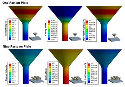
Figure 2. Part-scale prediction of hotspots, cooling rates, and melt pool volume using thermal simulation, which highlights the effect of printing multiple parts at once and the part’s geometry.
Alleviating Quality and Efficiency Challenges in Mass Production
In a mass production setting, manufacturing one part at a time is both time-consuming and costly. The optimal scenario involves maximizing the use of the build plate by filling it with as many parts as possible. However, the presence of multiple parts can have both advantageous and problematic implications.
One way in which parts affect each other is through thermal interaction when they are positioned too closely. Additionally, the scanning of layers takes longer when multiple parts are present. This extended scanning time serves as extra cooling time for each part before the next layer is scanned.
Figure 2 illustrates this behavior, in which nine inverted cone parts are printed simultaneously. A comparison with the single-part case in Figure 2 reveals significant reductions in hotspots, higher cooling rates, and smaller melt pools in the cone region. This is attributed to the prolonged additional cooling time, during which each part waits while the laser scans the other eight parts, particularly when these layers are already sufficiently large.
Optimizing Part Orientation Leads to Qualified Parts
The orientation of parts on the build plate significantly influences the quality and reliability of manufactured components. Take, for example, the hip implant replacement showcased in Figure 3, which offers many orientation possibilities. On one hand, positioning a part as flat as possible can mitigate heat dissipation challenges. However, this approach may not be optimal as it limits the number of parts that can be printed simultaneously. Conversely, orienting the part to occupy minimal space on the build plate presents the heat buildup challenge.
Hence, there exists a compromise between these extremes. To demonstrate the potential benefits of controlled overheating, consider selecting process parameters that induce approximately 1% lack of fusion porosity under normal conditions. In such instances, overheating can lead to a larger melt pool, effectively eliminating the lack of fusion that would otherwise occur. Simulations reveal significant variations in melt pool size, lack of fusion occurrences, and cooling rates based on different part orientations. These insights highlight the critical role of part orientation in achieving defect-free parts.
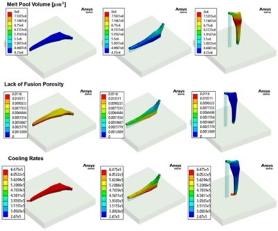
Figure 3. Part-scale prediction of hotspots, cooling rates, lack of fusion porosity, and melt pool volume using thermal simulation, highlighting the effect of the part’s geometry and orientation.
Working Toward Process Optimization
Nowadays, many FEA solutions offer seamless integration with optimization modules and techniques. This integration enables experts to perform automated optimization studies, paving the way for tasks such as determining optimal part orientation or estimating the ideal number of parts to be printed simultaneously.
Furthermore, gaining insights into the spatial distribution of defects and cooling rates within parts can greatly enhance the optimization of process parameters. This optimization may aim to prevent defects and achieve desired properties, especially in areas where high stresses are anticipated.
Learn how Mechanical software can help with your additive manufacturing needs.